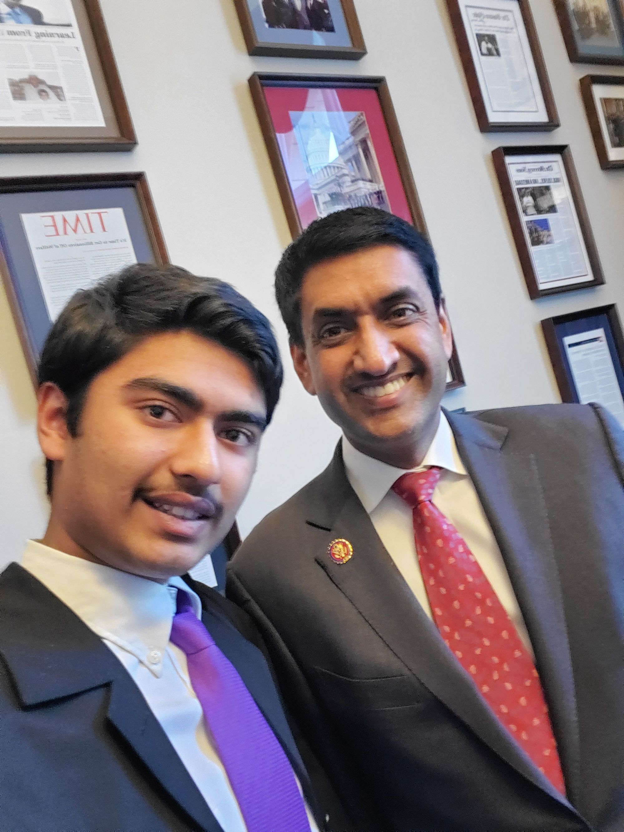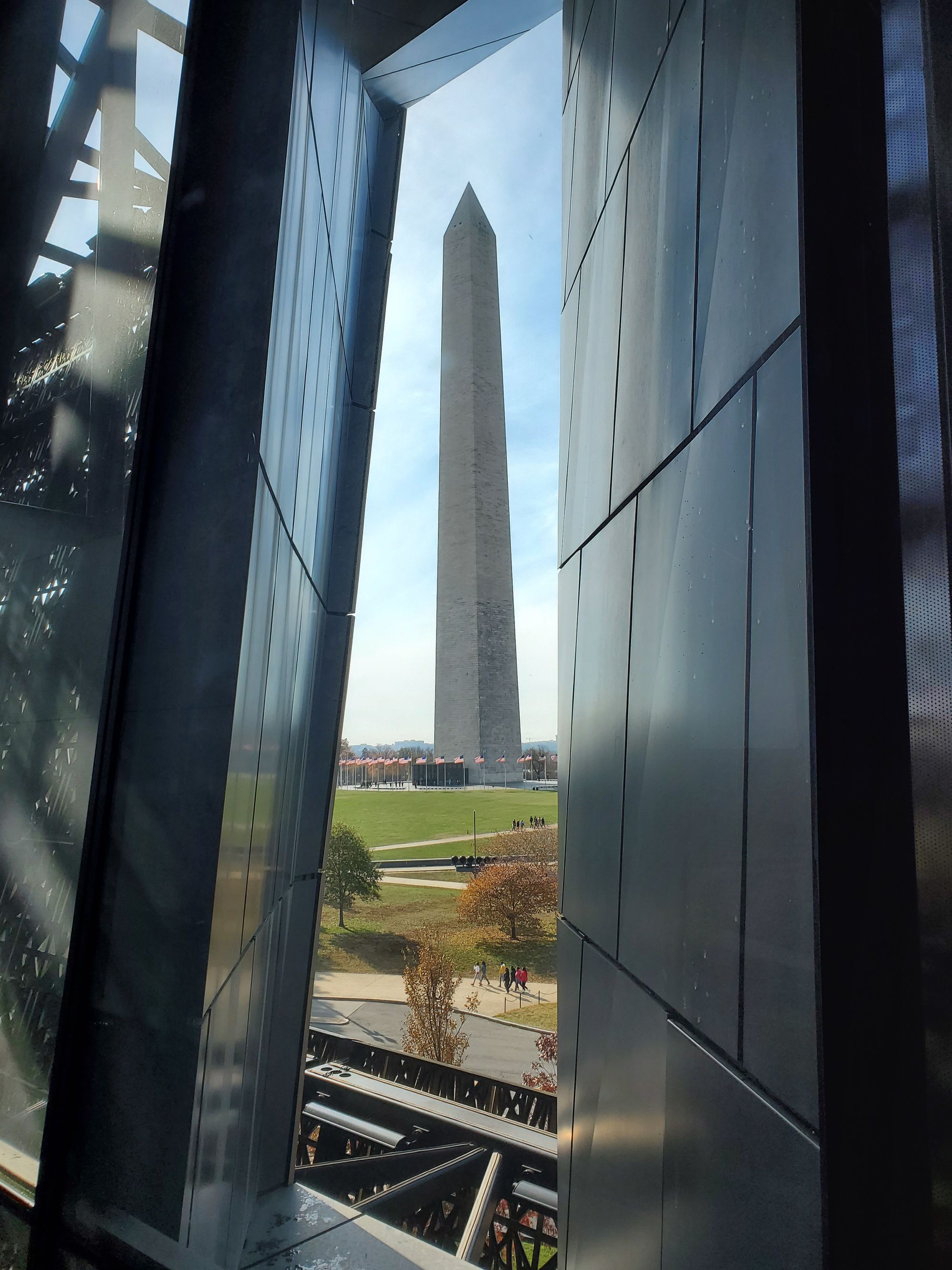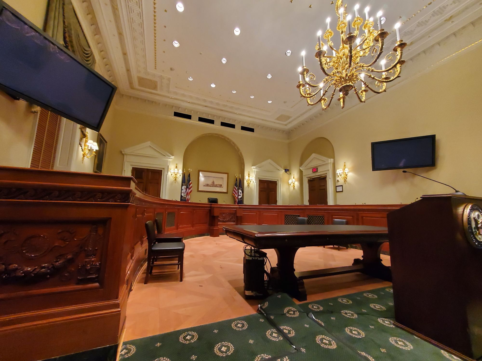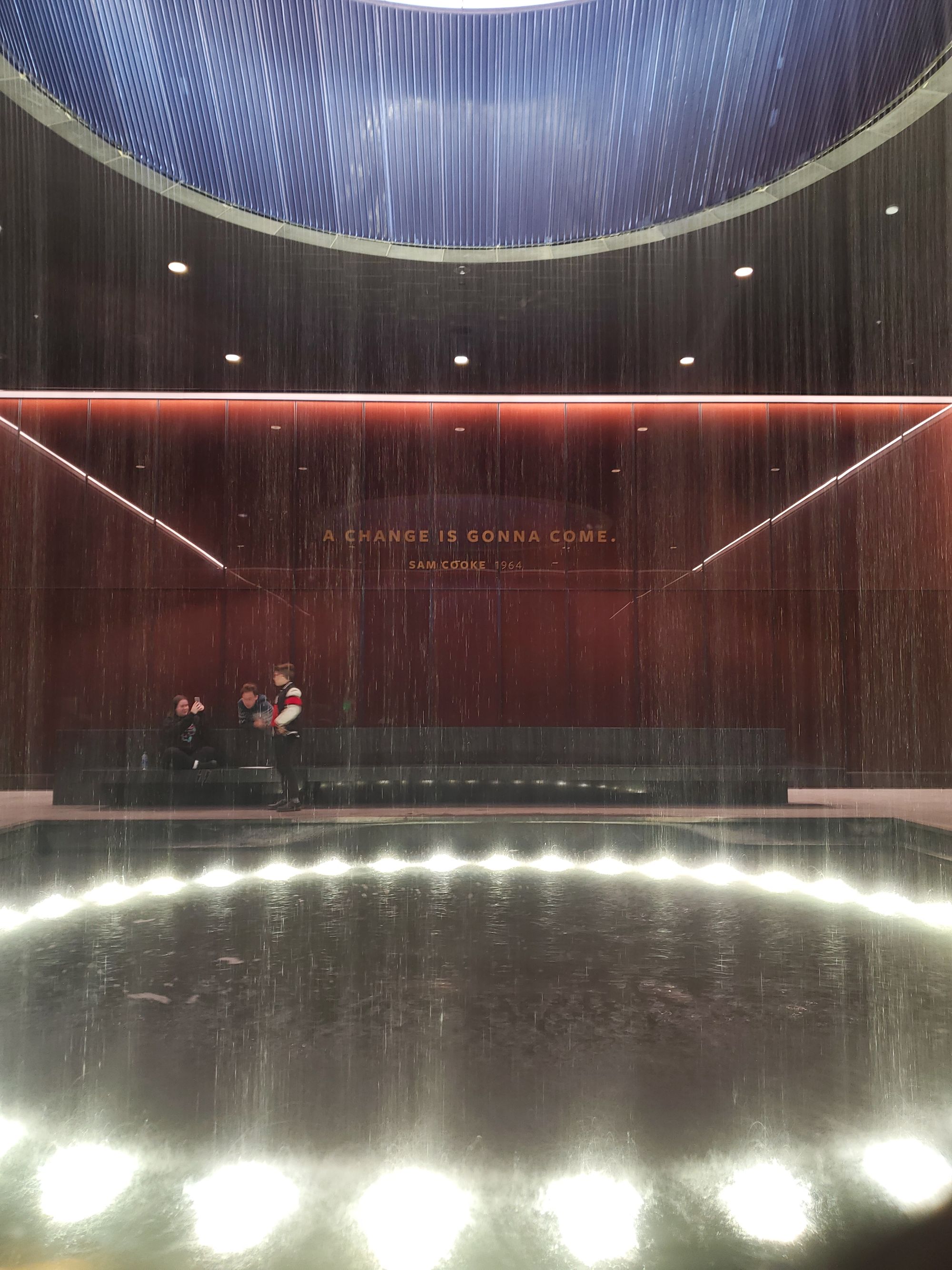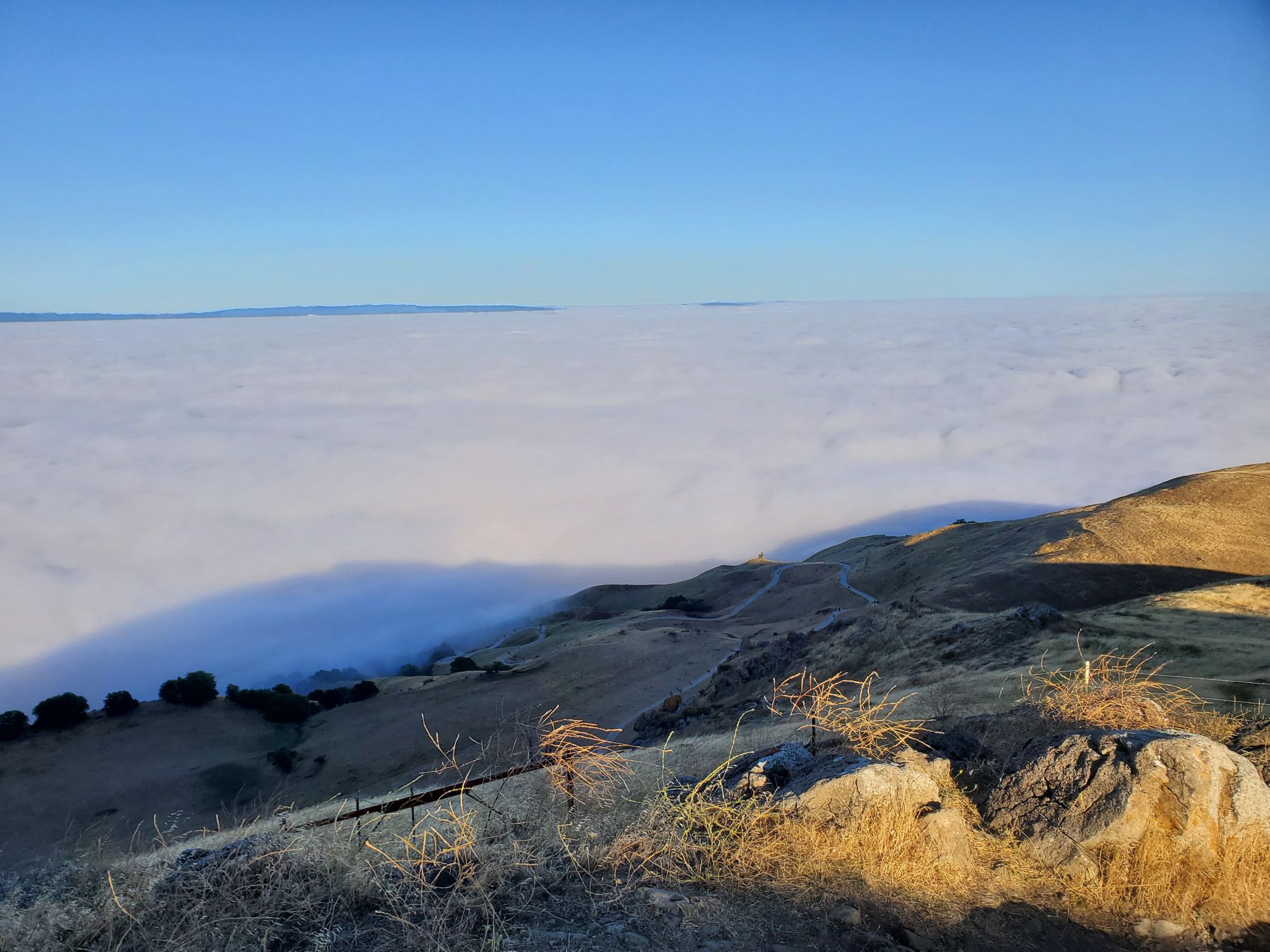
This 8 week internship—my first job—has been one of the hardest, yet rewarding experiences I've had.
I've enjoyed and learned a ridiculous amount from designing parts for and operating the DMLM (Direct Metal Laser Melting) 3D printers, performing solder fatigue analysis for commercial satellites, creating a deployment mechanism for a next-gen solar array that relies on 3D printed parts, and more...
How I got the Internship -
After my 2020 summer internship @ NASA fell through due to the start of the pandemic, I was determined to get an internship this summer. Applying for a summer internship as a high school student is exceedingly difficult, most big tech companies don't take high school students and many startups weren't hiring due to the pandemic. After cold emailing a dozen companies hoping for a response, I looked for other companies that may be accepting high school applicants in the midst of the pandemic.
I contacted one of my good friends who interned at Lockheed Martin Space the previous summer, and I asked him if get me in contact with the recruiter. After a month of waiting and another month of back and forth, I was finally asked to send in my resume. The recruiter was impressed and invited me to an interview. I prepared for a solid 2-3 hours for the interview and after the interview, I felt as if I killed it.
I got a call the next day with confirmation that I got the internship! I was beyond elated and accepted the offer that I got within the end of the week. I later got on a call with my managers and the recruiter, my manager told me what I will be doing during the internship and preparation for my first day.
My Expectations going into the Internship -
Going into the internship, I presumed I would be be mostly doing menial work and shadowing my coworkers. This would include creating presentations, filling out forms based on a template, etc. I was expecting to be assigned tasks and interacted with as a high schooler, rather than a college graduate.
I highlighted a few of the goals that I had going into my internship in my resume. I was hoping that I would be able to fulfill at least 2-3 of these roles to a limited capacity:
- Industrial Additive Manufacturing
- 3D modeling and fabrication
- Engineering Technician
- Proof of Concept design prototyping
- Contribute to research in aerospace
- Research in emerging technologies
- Gaining work experience in the industry
- Experiencing Start-up culture. (n/a for Lockheed)
My Internship Experience -
The First Day: Even from on first day, my expectations were blown out of the water. The first indication of this was my badge. My badge didn't say "High School Intern" or even "Intern", it said "Employee".
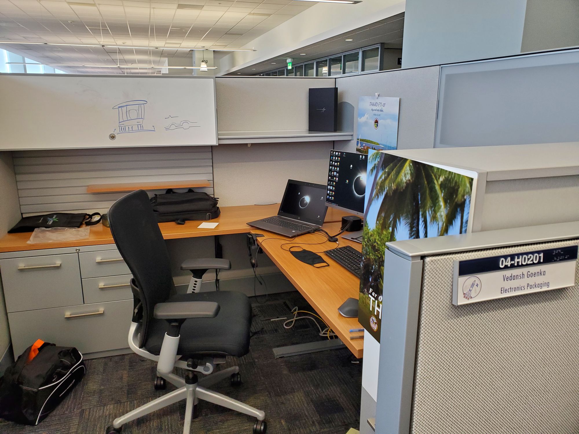
My manager showed me to my cube, which was huge! I was expecting to have a small desk that was recently vacated, but instead, I got a full on cubical– comparable to full-time employees–along with a proper engineering laptop and dual monitors. Not long after I settled in, I got my first assignment from my managers, I was to learn the basics of solder fatigue analysis with a co-worker and submit it by the end of the month. Rather than checking over someone's work, I was doing tasks given to entry-level, full-time employee!
Throughout the remainder of my internship, I wasn't given a SINGLE menial task, this means a lot to me. Every task that I was assigned challenged me in one of two ways: Either I would have to learn a whole new set of concepts, such as learning electronic components and their properties relating to solder joints, or I would be given a complex task and very little direct guidance–simply a list of criteria and constraints!
Additive Design Manufacturing Center
Working in the ADMC was a dream come true for me; over the past 7+ years, I have been obsessed with Plastic/Resin 3D printers and have ended up incorporating the manufacturing process into many of my projects–as you could easily tell from the rest of my blog; science fair, robotics, and even solutions to simple problems. Getting to work with metal 3D printers that are capable of 99.95%+ solid titanium, aluminum, copper, etc. was the highlight of my summer.
When I was first looking into internships, I remember reading about this article. This is the spark that made me want to intern @ Lockheed Martin Space over anywhere else.
After reaching out to one of the lead engineers at the ADMC, I was given a tour of the absolutely incredible facility. I immediately told him at the end of the tour that if there was any work that I could do here, I would love to do it. To my delight, he told me he would like me to work on some tasks starting the next day!
The least glorious and most tedious part of the whole metal 3D printing process is to recapture unused metal powder from the build plate (this is exponentially harder for larger printers, like the X Line 2000R I worked on). This is done through a cramped glove box that is made inert with Argon gas (to prevent spontaneous combustion of the powder) using a hose attached to a vacuum.
I set out to create a easy tool change system that would allow the operator to more quickly and more thoroughly remove metal powder from the crevices of the part. This not only saves hours of manual labor, but also cost since trapped metal powder that is removed in the vibration machine is oxidized, making it unusable. I fully dedicated myself to this task and was able to create the hose tool changing system in 2 days. After I got that working, I printed it out of plastic and tested it. It worked so well that the lead engineer decided to take it to other locations the following week!
Since the default configuration for the hose is attached to a lance (a large metal tube), I continued by creating a docking station that allows the operator to easily swap between the lance, and a custom tool–one that can easily be changed with the tool changing system.
The hardest part of the design process was designing a product that was all of the following at once; printable in plastic, printable in metal, air-tight, and quick to access. I spent 2 weeks and dozens of iterations getting the design tuned and finalized. I got to see a plastic prototype functioning in the machine, however due to a running print job, I wouldn't be able to see the final metal result.
In addition to designing the tool changing system, I was interested in the materials that were used to create isotropic 3D prints. I was shown to the "Universal Testing Machine", this machine was able to effectively pull on the material, in this case tensile bars that were printed scattered around the part. After measuring the cross-sectional area of each bar and loading it up into the machine, I would run the test.
After 10 minutes or so, the bar would snap extremely loudly and a stress/strain graph would be available. Using the material properties, elastic/plastic deformation, cross-sectional area, and other derived values, we would be able to certify whether the manufactured parts were within specifications.
In the process of doing this, I learned a lot about the different material properties themselves and different testing methodologies. After having some scholarly discussions about the material properties of different metals and how different fabrication/post-processing affect them, I suddenly realized how interesting materials science is. As I am writing this, I am pondering my path forward and contemplating whether I want to pursue material sciences further.
Working @ the ADMC was definitely the highlight of my time @ Lockheed. Looking back, I still find it incredible that my curiosity about 3D printing from Maker Faire in 5th grade has driven me so far!
Solder Fatigue Analyst
My first major assignment was that of a Solder Fatigue Analyst for the Electronics Packaging team. By the end of my internship, I had completed analysis on several boards for different satellites!
There are a huge variety of components that Lockheed Martin uses and for many of the components, different packages are available (such as leaded and leadless). For each of these packages, the parameters and equations to use widely differs; I taught myself from documentation which formulas to use for accurate results.
After I got a package list from the list of components on the board–a process of its own, I performed the solder fatigue analysis using Excel and corresponding formulas for the package. For packages that would fail prematurely into their life, I wrote recommendations into a Powerpoint that outlines when it would fail and some alternative packages. If the package needs to be modified as well, I indicated the modifications needed for the package to pass. I presented the powerpoint, which contained the results from my analysis and any recommendations, to the PCB Engineers and answered their questions. Besides the initial board, this entire process was completed by myself.
The biggest takeaway for me was not the skills or lessons I learned, rather it was the systems-level understanding I developed regarding the design requirements and validation standards for any space-bound body due to the relentless hostility of space. I participated in various tours–thermal vacuum (TVC) testing, to name one–and many of the questions that I had about projects that I was supporting (or learning about) were about the reasons for design decisions. Solder fatigue analysis is one such area, most boards simply don't experience the frequent, extreme temperature gradients that satellite boards do.
Deployment Mechanism for 3D Printed Solar Array Truss
Due to the cyclical nature of my workload, I asked my manager for another project, preferably one that included elements of CAD, rapid prototyping, and moving assemblies. The next day, I was brainstorming a complex deployment mechanism with a fellow post-graduate intern that sits behind me.
Without going too far into the specifics of the project, there is a Solar Array that is suspended from the ceiling on a linear rail track. While the solar array is able to deploy on its own due to the existing innovative "spring" design, the linear rails at the top are over 50 years old and prevent the truss from deploying.
As part of the demo that we needed to perform for our customer, we wouldn't be able to assist the deployment of the structure in any way. The biggest problem was gravity, we needed to simulate a zero-gravity deployment in a regular clean room.
The solution that my coworker and I came up with was a multi-pulley system that assists the deployment of the truss without human intervention (as there wouldn't be any in space).
We spent the next 2 weeks iteratively designing our vision in Creo Parametric 4. I originally hated this CAD software, to even create simple structures (like threads) or patterns, would take a bunch of supporting features. Even after learning the software well, I still hate it; however, I've grown to appreciate certain aspects of it– such as its implementation of the middle click.
After each part was designed, we would upload the print over to the innovation garage's–the local makerspace with 3D printers, routers, tools, etc.–3 working Prusa i3s. One of us would run down and start the print and watch the first layer go down and tune the printer if needed. Our workflow was pretty much: design–review–print–test–revise. After 5 revisions, we had a working prototype and made our final deliverable 4 weeks early!
Besides the knowledge that I gained as part of the assignment, I furthered my ability to self-learn, to concisely and precisely ask questions, and to communicate complex, abstract ideas with my coworkers.
My Takeaways -
As mentioned earlier, I was under the expectation of meeting a few of my goals for the internship to a limited capacity, however, by the end of the internship, I had met practically all of them!
- Industrial Additive Manufacturing - ADMC
- 3D modeling and fabrication - ADMC/Solar Array
- Engineering Technician - ADMC/Solar Array
- Proof of Concept design prototyping - Solar Array
- Contribute to research in aerospace - ADMC/Solar Array
- Research in emerging technologies - ADMC/Solar Array/Solder Fatigue
- Gaining work experience in the industry - ADMC/Solar Array/Solder Fatigue
Looking back, the time that I spent working was 100% worth it. I not only gained valuable work experience in the areas that I am passionate about, but also connected with amazing people that appreciate my curiosity and are more than willing to dedicate their time to help me learn.
Working with professionals, I got to experience first-hand the true dedication and professionalism that is apparent in the workplace; Including how to effectively communicate professionally with my coworkers–I was unsure at first and ended up calling a manager as I would call a teacher.
I also have greater clarity in my career direction/major. I was initially focused on being a young entrepreneur and minimizing my time in industry. Additionally, I wasn't as interested in doing research and thought to favor more tangible work, such as design or fabrication. Due to the internship, my opinions and inclinations have definitely shifted. I learned about technology readiness level (TRL) during a chat with my coworker from the ADMC (we were visiting the Palo Alto Campus), TRLs are used in industry to decide whether technologies are ready for missions, but I found that this metric fit really well into my interests.
Being an entrepreneur would be the equivalent of bringing an idea from TRL 1 all the way to TRL 8 or 9 as fast as possible. While I am still interested in doing that, I'd now like to gain more experience in the lower TRL levels. Much of the work that I have been doing has been in the higher TRLs–designing, fabricating, and machining parts. I've already had experience in the 6-9 range, however, my direct experience in the 1-5 range is limited. This is where I think I will be able to grow the most.
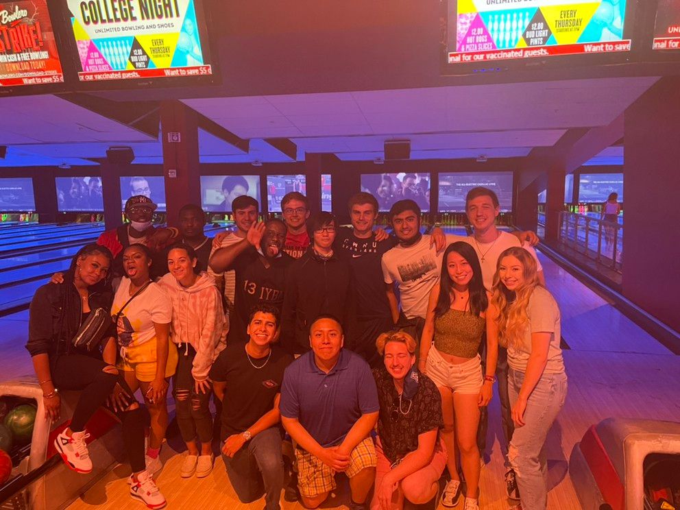
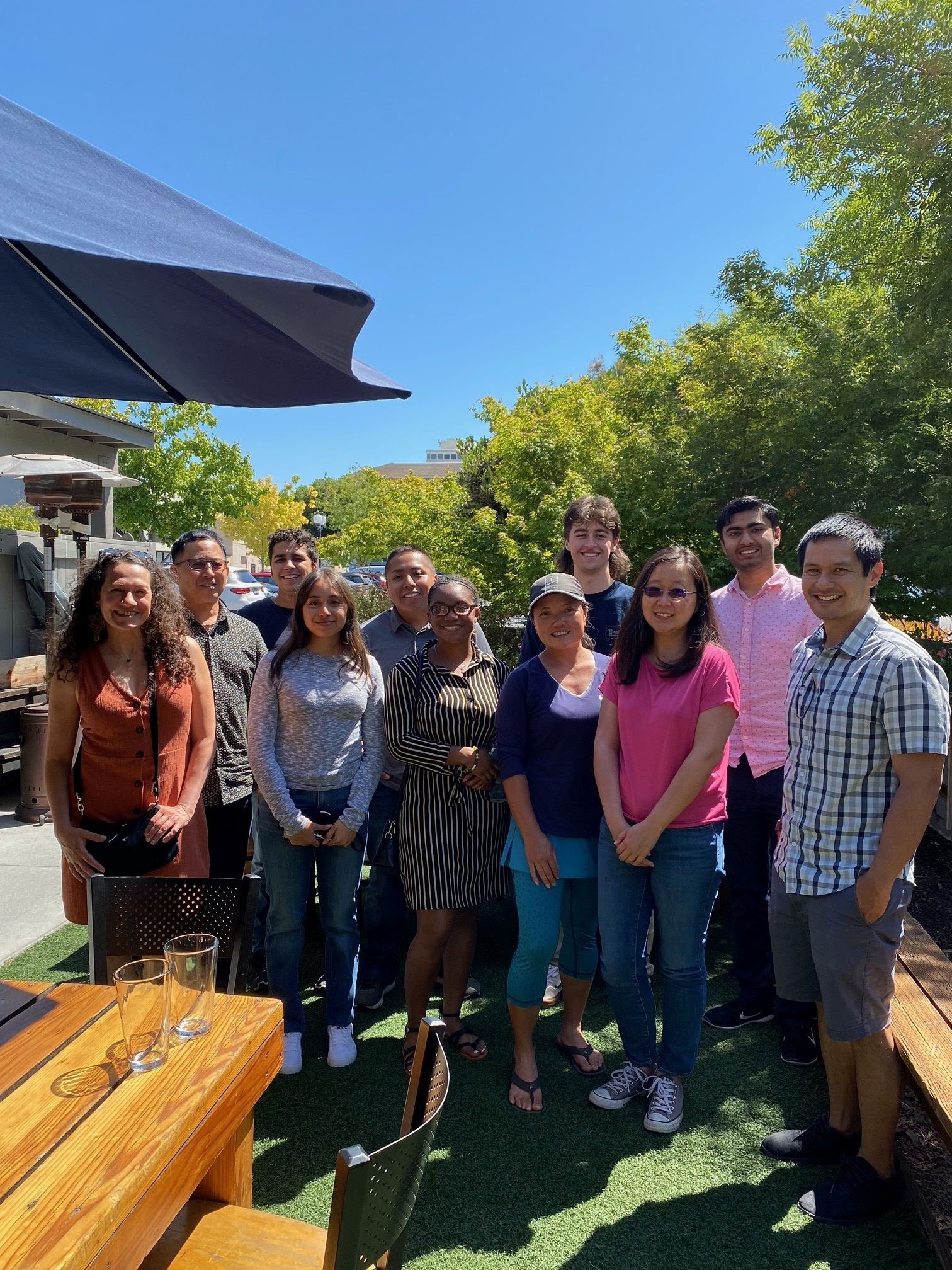
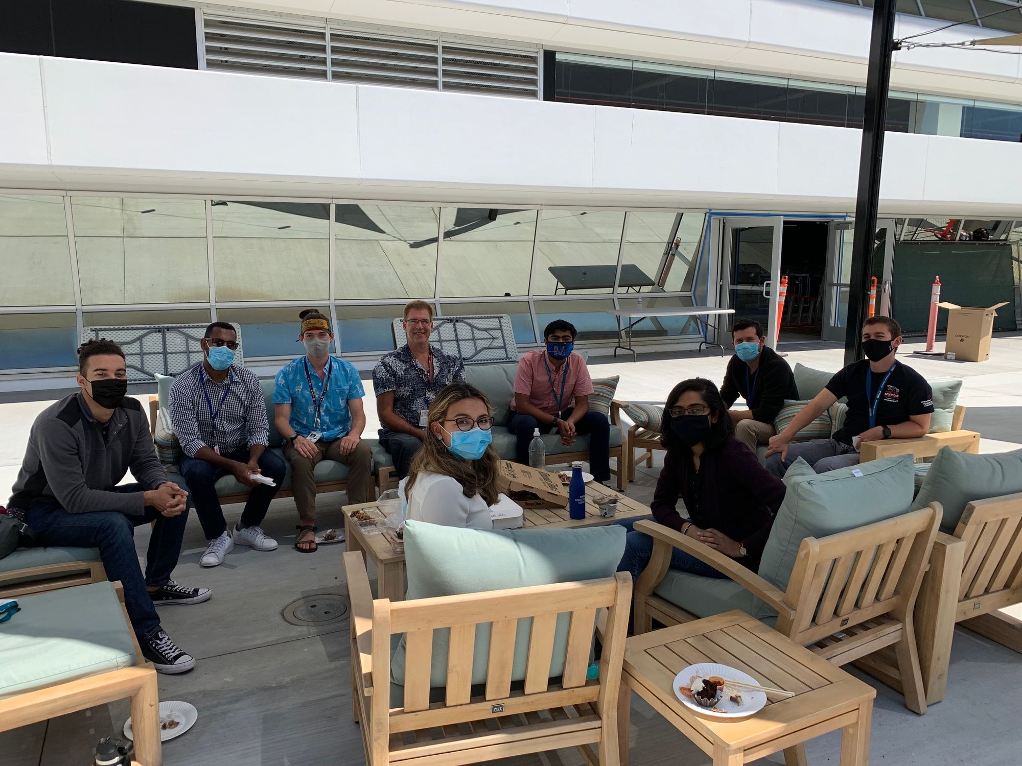
Photos -
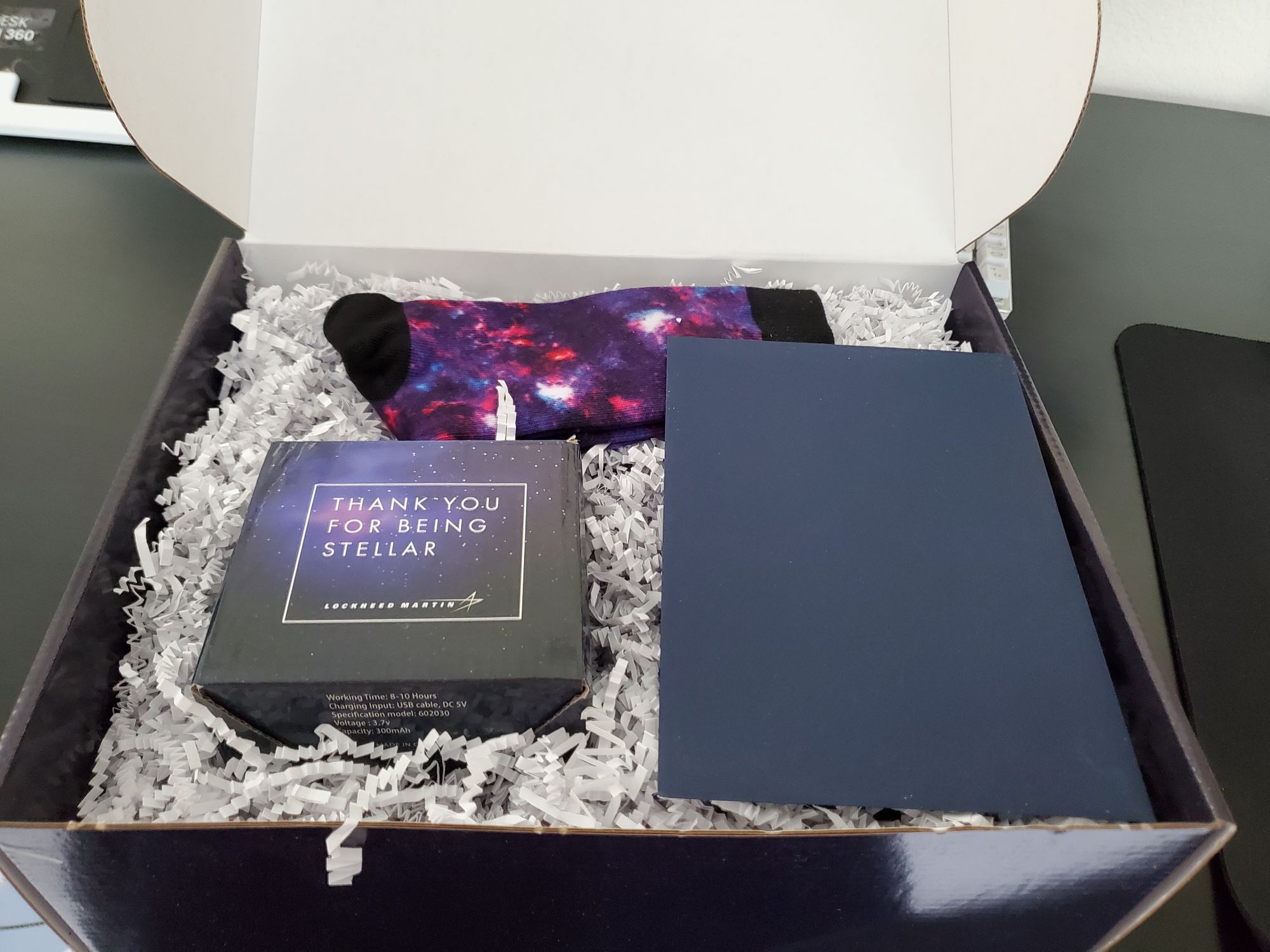
As a parting gift from my co-workers, I got a really cool 3D printed desk item that is made of solid metal!

Ideation

The easiest solution to the problems that I have mentioned above is designing and 3D printing a phone mount for my bike. This way, I don't have to wait 2-5 days for some absurdly expensive piece of plastic.
Rather than start designing, I first looked through Thingiverse and PrusaPrinters for good designs. After looking for a while, I didn't find anything that really caught my eye. So I decided to make it myself.
Instead of making some complex slider mechanism, I used a Phone Tripod Mount that I have printed before. I really like the clamping mechanism that this design uses, and decided to make this the base of my design. Why reinvent the wheel?

Optimizing Phone Holder
I started by importing the STL file into Fusion 360 and converting it, which is a extremely tedious and boring process, to a BREP. This makes it much easier to work with and edit. I started with the base as this was the most critical part. I decided that I would effectively add vertical shaft near the center of mass to accomodate a bolt and nut.



I then spent too much time adding fillets to make the part stronger.


Once these essential tweaks were made, I added the hole for the bolt. The bolt is going to be added from the bottom (through the clamp that holds this to the bike) and into this phone clamp. To do this, I made a clearance hole, and a hexagon shaped hole for the nut. This was crucial to get tight, as the plastic will be serving as the "wrench".


After realizing that I was working in CM and scaling the model down by a factor of 10:1. I started working on the other parts.
The knob was fine the way it is, so I just left that alone
For the slider, I just added some fillets for strength and looks

Bike Clamp
The clamp was the hardest part to design, probably because I was making it from scratch unlike everything else.
I started by sketching the rough shape. I had considered a lot of mounting methods, I settled on a modified hose clamp as it seemed the easiest and most reliable to implement. Additionally, making changes would be quite simple based on the diameter of the attachment point.
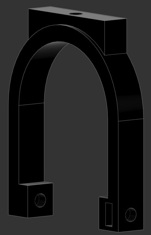
The sketch below, and for that matter the clamp in general, was designed to fit around a 35mm "tube".

After adding a surface for the phone clamp to attach to, I was left with a shape like this:

I added the hole at the top for the bolt to go through, this would be for the same bolt as the one in the Phone Holder.

With that done, I started adding the actual clamping mechanism. By designing this to be printed on its end, the direction of the layer would not compromised the integrity of the lock. This is a fundamental concern that all designers should keep in mind when designing for most additive manufacturing processes, the exception being DMLS (direct metal laser sintering), although those parts are often baked, to a similar effect as annealing, which helps further bond the layer together.
First, I added a space for the bolt to go.

Next I added a slot for the nut to go into. Rather than having a hexagon shape, I made a receptacle for the nut to into. This would mean that the nut won't as easily fall out, and that I can just use a piece of electrical tape to completely eliminate the risk. Here is a section of the internal structure that keeps the bolt:

The only additional hardware needed with this design are the following:
- M3 x 15 MM
- M3 x 35MM (30 works)
- Two M3 Nuts
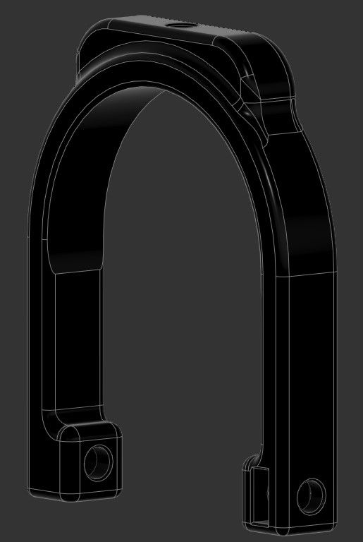
With that, I went ham on the fillets. This makes the design look a lot cooler and stronger, as there aren't any hard edges to take impact or start a crack on. I also made a parameter for tolerances that way iteration, if necessary, is much easier.
Render
To cap it all off, since I did decide to publish the design on PrusaPrinters and Thingiverse, I made a few renders. I have attached some of my favorites below. In addition, the printed and installed design. Finally, the design files are below that.
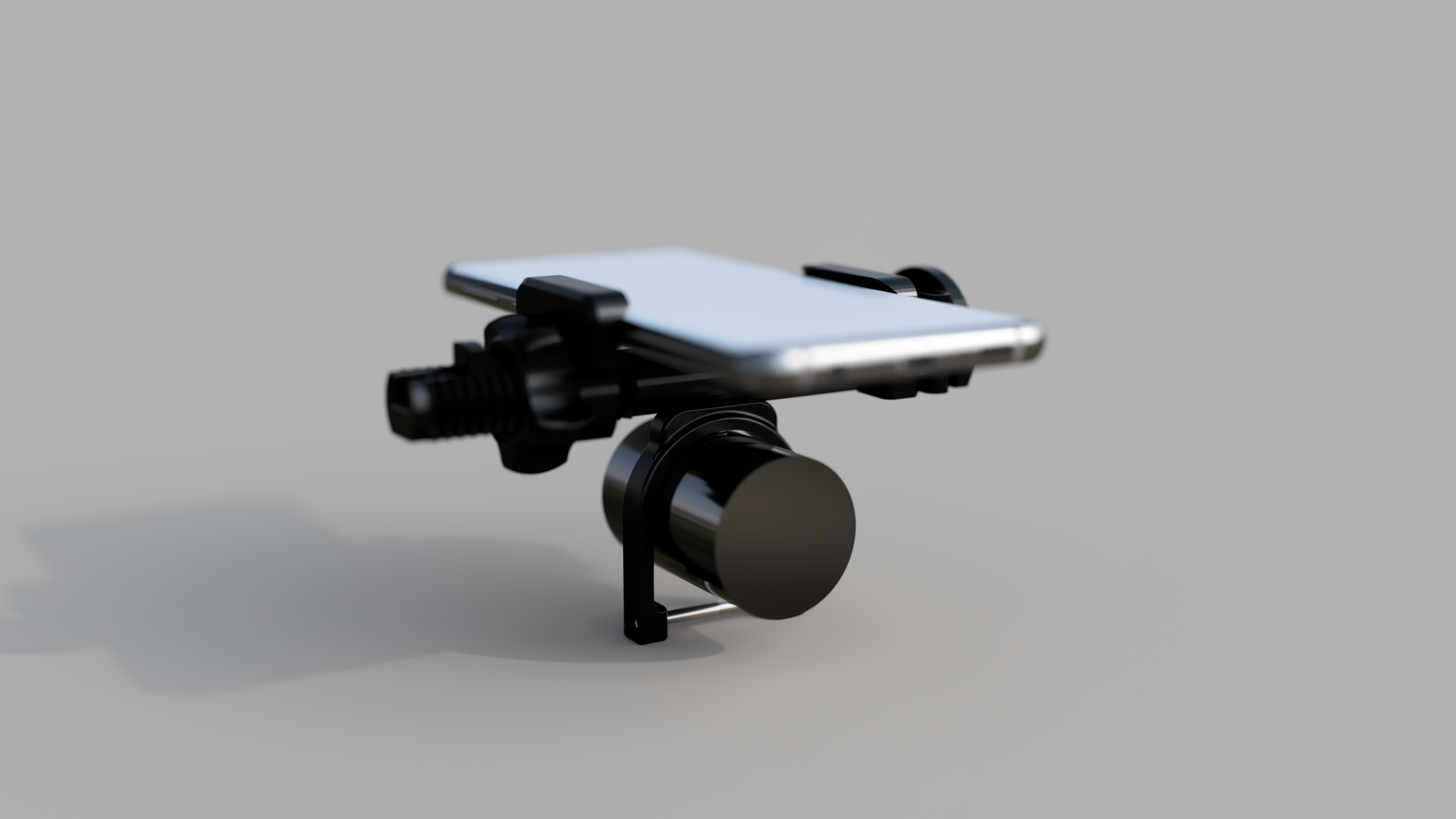
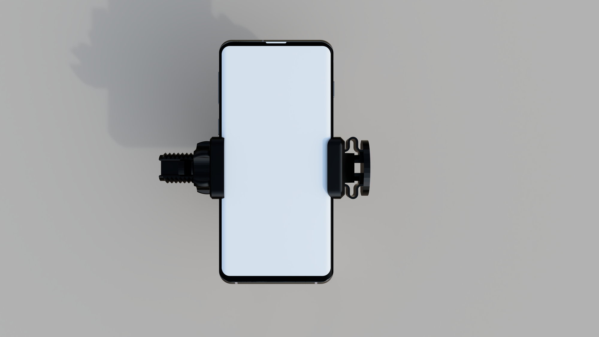
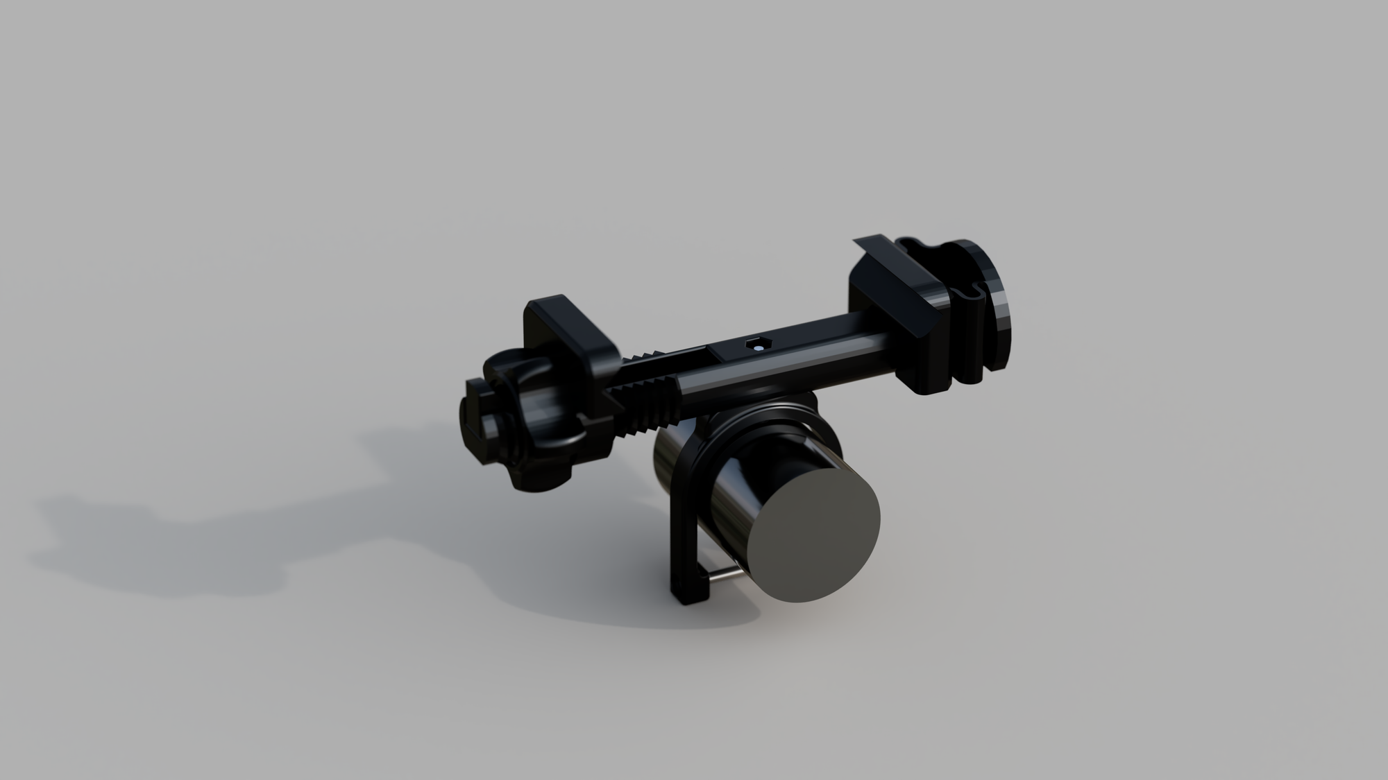
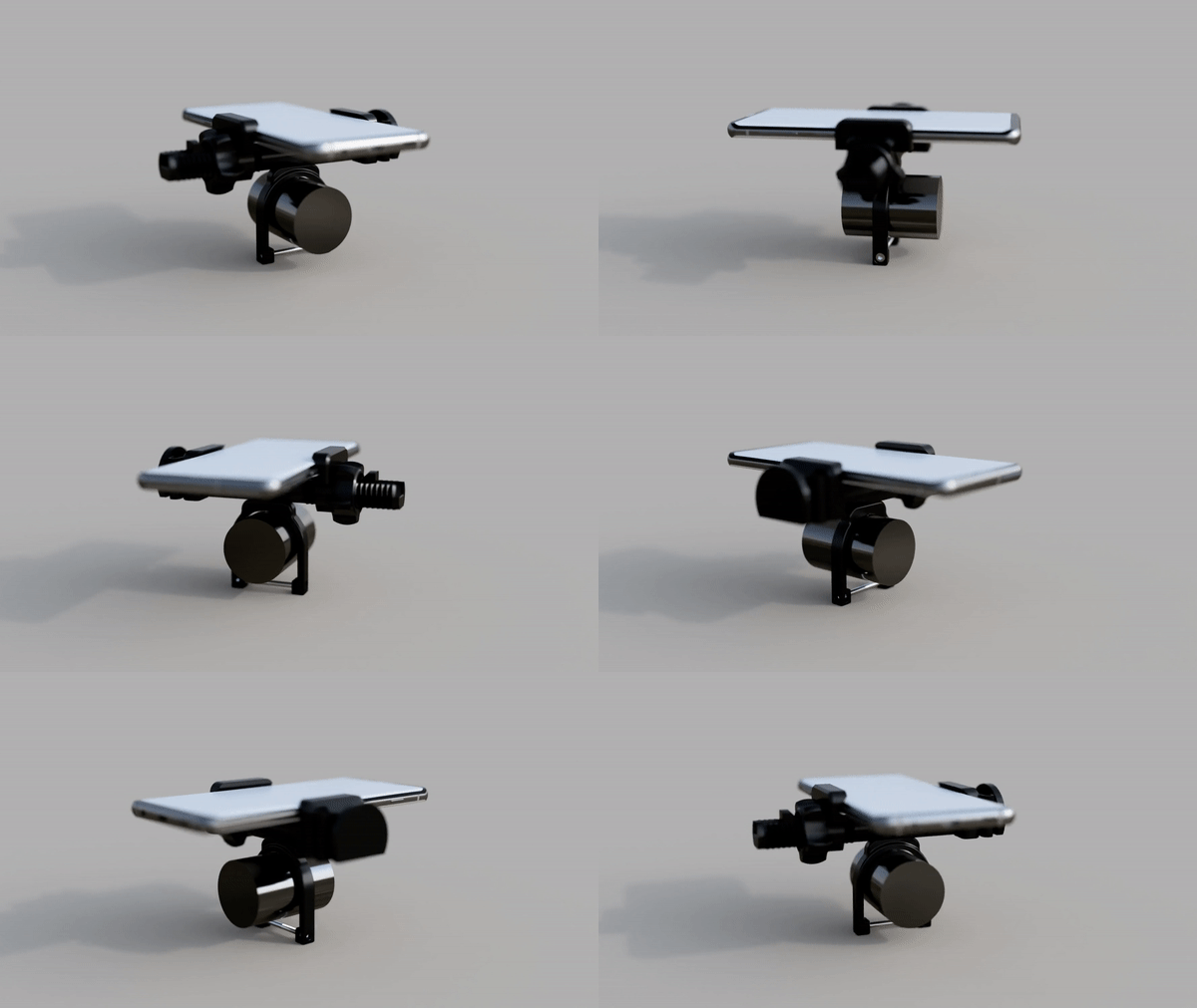
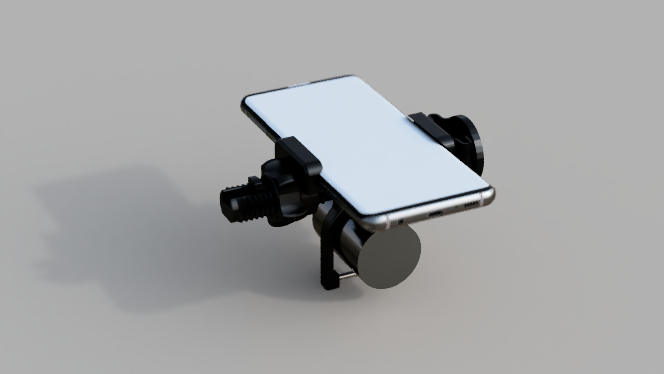
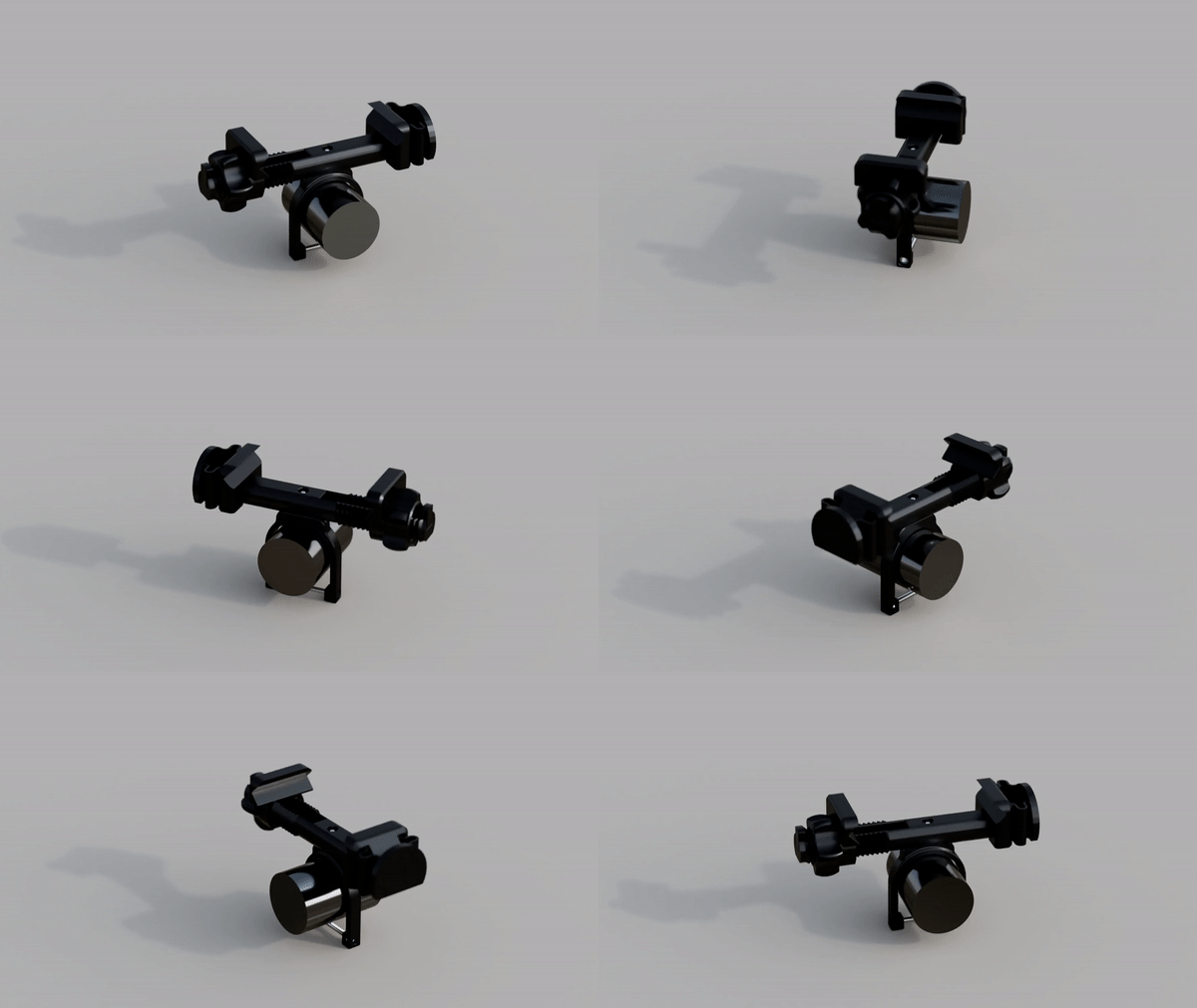
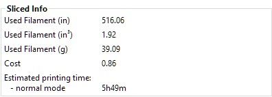
Installed!

Design Files (Google Drive)
Thingiverse Link
PrusaPrinters Link
]]>I've taken snippets of code and of other similar guides to compile this guide. All references are at the end.
This guide assumes basic knowledge of linux commands. If you are unsure, please refer to the man page of each command.
Step 0: Prerequisites
Upon completion, this server should be able to the following:
- Automatically download all your favorite TV shows and immediately after they air/become available
- Have all of your media neatly organized and named consistently
- Be able to network stream content to any device
Hardware Needed:
- Raspberry Pi 4 (2gb +)
- Micro SD Card (16 GB minimum; 32 GB recommended)
- Hard Drive or SSD (Ideally 2+ TB)
- USB 3 Enclosure for Hard Drive/SSD
- All necessary cables (power, data, network, etc.)

Software that will be used:
- OS: Raspberry Pi OS (32 bit) Lite
- VPN: Private Internet Access - OpenVPN w/ IPTables
- Torrent Client: Deluge
- Movie Fetcher: Radarr
- TV Fetcher: Sonarr
- Subtitles Fetcher: Bazarr
- Tracker Consolidation (Optional): Jackett
- Media Solution: SMB Sharing via Samba and/or Jellyfin (not covered)
1 Basic Setup
Download the OS file and use balenaetcher, or your tool of choice, to format the SD card into a bootable disk.
Insert the SD card into the Raspberry Pi, and start connecting the wiring, do NOT connect power yet.
You should have the following devices connected to the Raspberry Pi: Display Output, Ethernet, Keyboard, Hard Drive Enclosure (with Formatted Hard Drive inside), and optionally a mouse.
Take note of the IP Address on LAN: 11.1.1.175
sudo apt update
sudo apt upgrade -y
sudo apt autoremove -y
sudo raspi-config
The following must be done in Raspi-Config:
- [1] [3] Password
- [1] [4] Hostname - I changed to Piplex
- [1] [5] Boot Status - I changed to Boot with Login
- [3] [2] SSH - MUST enable
- [5] [2] Time Zone - Optional
- [5] [3] For Logitech K120 - Generic 104 key - Other - US - English US - First Option for both
- [8] Run once before rebooting
Reboot the Raspberry Pi
sudo reboot now
1.1 Static IP
For setting up the Static IP I followed this guide. Here are the necessary steps:
Let’s first retrieve the currently defined router for your network by running the following command.
ip r | grep defaultBy using this command, you should get a result similar to the one we have below.
default via 192.168.0.1 dev eth0 proto dhcp src 192.168.0.159 metric 202
Make a note of the first IP mentioned in this string.
Next, let us also retrieve the current DNS server.
sudo nano /etc/resolv.confFrom this command, you should see the lines of text below.
# Generated by resolvconf
nameserver 192.168.0.1
Ctrl-X to exit
Make a note of the IP next to “nameserver“. This will define the name server in our next few steps.
Now that we have retrieved both our current “router” IP and the nameserver IP we can proceed to modify the “dhcpcd.conf” configuration file by running the command below.
This config file allows us to modify the way the Raspberry Pi handles the network.
sudo nano /etc/dhcpcd.confWithin this file, enter the following lines.
First, you have to decide if you want to set the static IP for your “eth0” (Ethernet) connector or you “wlan0” (WiFi) connection. Decide which one you want and replace “<NETWORK>” with it.
Make sure you replace “<STATICIP>” with the IP address that you want to assign to your Raspberry Pi. Make sure this is not an IP that could be easily attached to another device on your network.
Replace “<ROUTERIP>” with the IP address that you retrieved in step 1 of this tutorial
Finally, replace “<DNSIP>” with the IP of the domain name server you want to utilize.
This address is either the IP you got in step 2 of this tutorial or another one such as Googles “8.8.8.8” or CloudFlare’s “1.1.1.1“.
Append this to the bottom of the file in the following format
interface <NETWORK>
static ip_address=<STATICIP>/24
static routers=<ROUTERIP>
static domain_name_servers=<DNSIP>
My config was the following: (8.8.8.8 was for PIA)
interface eth0
static ip_address=11.1.100/24
static routers=11.1.1.1
static domain_name_servers=8.8.8.8 11.1.1.1
Prior to restarting, run either:
hostname -I
or
ifconfig
This will spit out the current IP address
sudo reboot now
After rebooting, check that this has changed.
1.2 Key Verification
Another tool that is useful to set up is Key Verification, this allows us to skip entering our password when we enter.
I ran these commands in Powershell from my C:\Users\Vedan\ folder to add the key to piplex.
ssh-keygen -t rsa -b 4096 -C "youremail@example.com"
ssh pi@piplex
mkdir .ssh
exit
cat id_rsa.pub | ssh pi@piplex 'cat - >> /home/pi/.ssh/authorized_keys'
1.3 External Drive Mount
Let's now mount the external hard drive to the Raspberry Pi. I have used this guide to set this up.
USB drives should be automatically mounted when it is connected to the Pi. If you want to check where your drive has been mounted, you can simply use the following command.
sudo cat /proc/mountsI wasn't able to find my hard drive, so I had to look for a troubleshooting step.
I added the following lines before exit 0 in /etc/rc.local
sleep 20
sudo mount -a
2 More Networking
Next let's set up Samba Shares. This should allow us to access the filesystem of the Raspberry Pi from any device on the network. I used this guide to set up Samba.
We can install the packages that we require to setup Samba by running the following command.
sudo apt install samba samba-common-binThis will install approx. 20-50 packages and their dependencies.

References:
]]>






The Mostly Printed CNC (MPCNC): a project that serves as a capstone to the passions that I have cultivated over the years. I discovered this project during the research process for my 3D printer. Over the course of my research, I developed strong affinities towards a selection of YouTube content creators, many of which I still watch in my spare time. One of these YouTubers, Teaching Tech, detailed his journey to create, mod, and use a MPCNC, specifically the Lowrider 2 model.
Over the course of late 2019 and early 2020, the MPCNC stayed as an afterthought in my mind, occasionally coming to the front and offering an interesting conversation topic. During the tail-end of the ill-fated 2019-2020 FRC season, our team was discussing the possibility of purchasing a metal capable router as changing the CNC set up from bar stock to plate stock took an extremely tedious ~1 hour. During the longer meeting this often wasn’t a huge concern, but during shorter meetings where the queue was as long as the meeting, this one hour queue always left some groups dissatisfied and without fabricated parts. After Covid-19 prematurely ended the season, talks about purchasing a CNC router grew with the administration, but were ultimately shut down due to the exorbitant costs and the seemingly little value.
When I caught wind that the router proposal had died down, I decided on a moonshot idea: to write up a quick pitch for the LowRider 2 CNC and market it as not only a metal-capable CNC router, but also a learning experience for whomever is involved in its construction. I was invested in the concept, but I never expected to receive the overwhelmingly positive feedback from the mentors that I received. This extended to the administration and by the beginning of summer the MPCNC was a go. Here’s the one pager that I used in my pitch: Lowrider CNC Plans
In parallel with my other projects over the summer, I spent weeks perfecting details of the construction and part selection of the MPCNC. One of my close friends had seen the potential of the MPCNC and decided to build one for his guitar-making hobby—he wants to turn this into a side business. When he surprised me with his progress I felt a wave of mixed emotions: shock, amazement, pride, and even a tinge of betrayal, but these quickly subsided and were replaced with another emotion: ecstasy. I was wholeheartedly interested in how he did it and used him as motivation to modify parts and try to out do what he had accomplished.
Sending my proposal to mentors and school administration during the peak of summer I wasn’t expecting a reply, but I got one within a few days, however, it contained bittersweet news. The CNC was fully approved—the sweet— but due to Covid-19 the legal department of the school was still trying to collect its marbles regarding sending (potentially) dangerous tools home with a high schooler. I was devastated by this, as I thought this was the school’s way of saying, “Yo that’s a cool idea and if Coronavirus wasn’t a thing we’d definitely get one for y’all, but since, well Coronavirus, we need to pull the plug on this... indefinitely.” After continually checking in with the robotics mentors bi-weekly I got disheartened and eventually stopped asking.
Summer ended and distance learning began, during one of the weekly robotics meetings I was pleasantly surprised, the CNC was being approved as a project. What followed was a long series of logistical emails and changes to the format of the project. The CNC was gonna be a multi person project, then it became a single person project at the robotics lab, and after a few other format changes mostly due to the severity of Covid-19 the final format was decided: I would take the kit home and work on it in my garage. In mid-November I went to the lab and picked up the filament and started the ~60 hours of printing. Shortly before winter break, I went in and picked up the supplies for the actual CNC, the metal, the motors, the fasteners, the bearings, etc.
The Build: Written on Day of or Day after.
Day 1: 12/19-12/20
Finally! After almost a year (10 months) of trying to persuade the administration and mentors and trying to find a “Covid-19 friendly format” I finally had the CNC in my hands and boy was I excited to start.
I started off by inventorying all of the parts to see if anything was missing, this did not go as planned. For the motherboard that I bought, the stepper motor drivers needed to be purchased separately, and in a fantastical miscommunication (I still don’t know how this happened) rather than buying the required 5 that we needed (or 8 to save on costs), we ended up purchasing 24—keep in mind that each of these cost ~12 dollars... Besides this everything seemed to be there and I was ready to proceed.
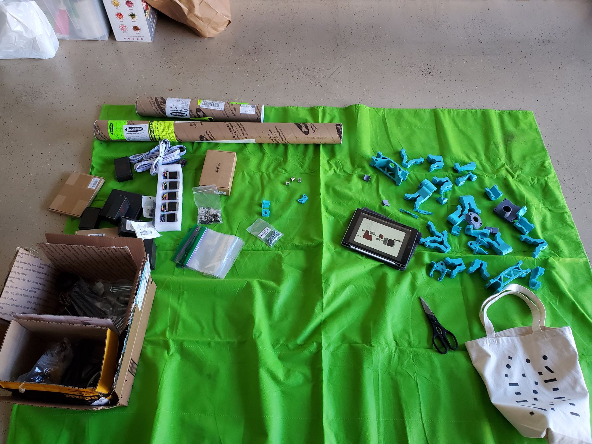
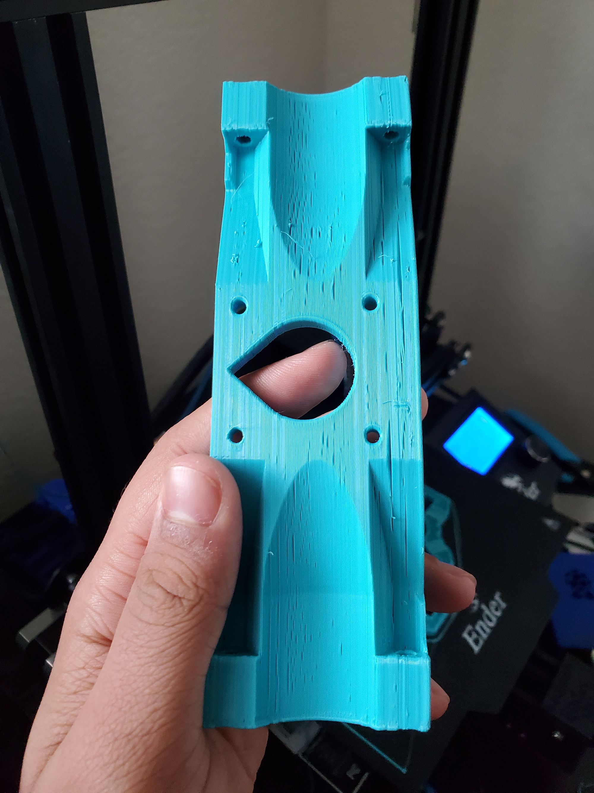
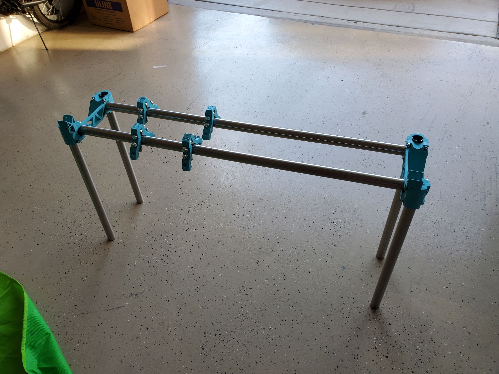
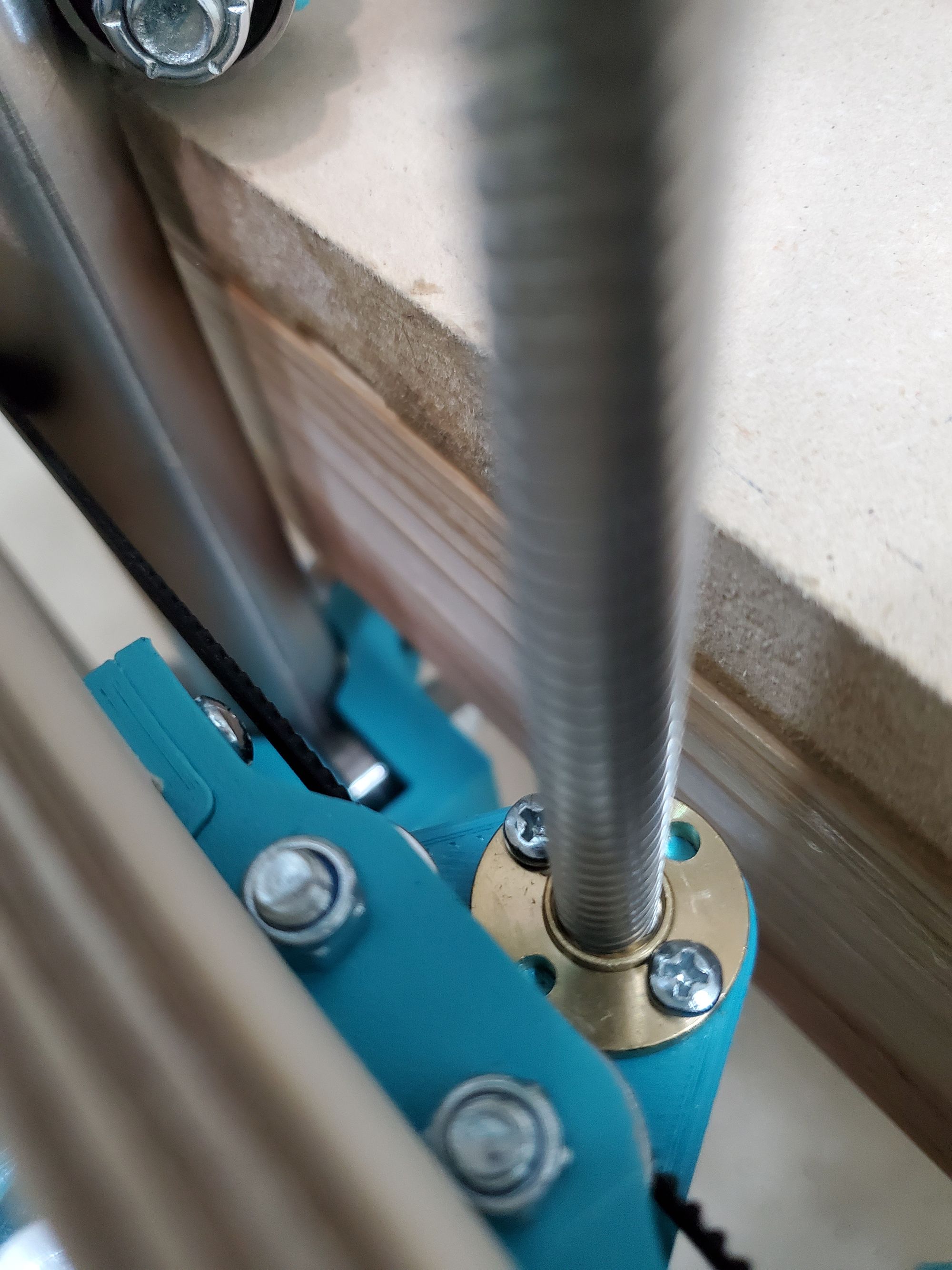
I started off my organizing all of the nuts and bolts into ziploc bags for easy access. Then I started off by assembling the frame. This was something that took a lot of finesse. For each of the parts I need to hold 2 heavy metal tubes securely while putting a thin 3d printed spacer between them and also tightening 4 bolts evenly (with a lock nut that wasn’t a captive nut). With my dad’s help, the cracking of two of the 3D printed pieces—this shouldn’t have any impact on the machine, and about 3 hours, the frame was ready and assembled. I also need to add the x -rollers, this took significantly longer than I expected. The bolt had to go through plastic-bearing-plastic (or nothing here)-locknut and with the tight tolerances tightening this assembly took a lot of time as I needed to make around ~10 rotations to get adequate pressure. Each bolt took ~7-8 min to do, this may seem like not that big of a deal, but for just the 4 rollers (pictured below), I need to do this 12 times (+ 4 more as I forgot to put them in while tightening the rails).
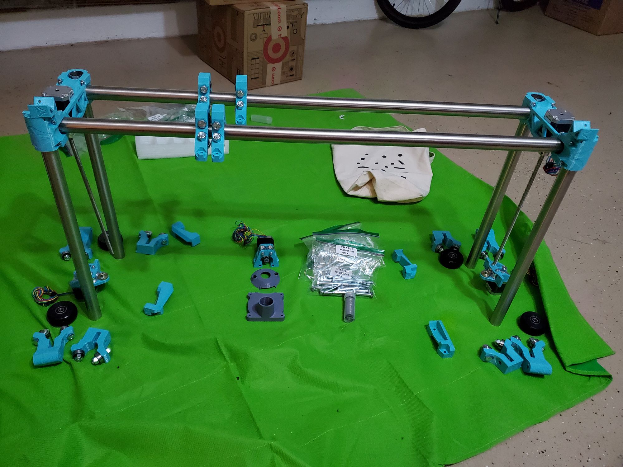
I then had to continue this bolt- plastic-bearing -plastic-lock nut combination for 16 other components (for the Z axis, where Z is up and down). This ended up taking me to the end of Day 1 for two reasons: One, it was 9 O'clock and I skipped lunch, making me really hungry. And Two, I had done almost everything I could have done with the parts that I had. I still needed CNC’d wood for the side panels and the carriage (the irony of needing CNC’d wood for a CNC. This left me with a rough assembly that looked like this:
Day 2: 12/22
After my friend, the one who built the CNC over the summer, used his CNC to cut the plywood I needed and dropped it off I was able to continue the building process. The holes that he drilled, while in the right spot they were nowhere near the right size. To combat this I had to drill the holes out, but this presented a problem: drilling plywood has an extraordinary chance of splitting, considering that the holes were on the edges of the work, I couldn’t follow any method that I knew about drilling the plywood. I didn’t have other pieces of wood that I could use as sacrificial surfaces to prevent tear out (I think that’s the technical term). I had to improvise and since I didn’t have any spares I had to be extremely careful. After a moment of deliberation I tried a few things. Rather than using the final hole size drill bit I worked my way up, but when I tried to drill the hole the plywood started to chip, dang, that was the only “legit” method that I could think of. I then tried something that I remember being told not to do, as it was considered a poor idea—woodworkers avert your eyes! I ran the drill bit, starting with a smaller size, in reverse until I had slowly gone through the board, only after I did this, I was able to turn the drill in the right direction and clean up the hole. For each of the 8 holes I had to step through 3 sizes of drill bits paying 110% attention to make sure that I didn’t accidentally wreck these irreplaceable pieces of wood—talk about stress!
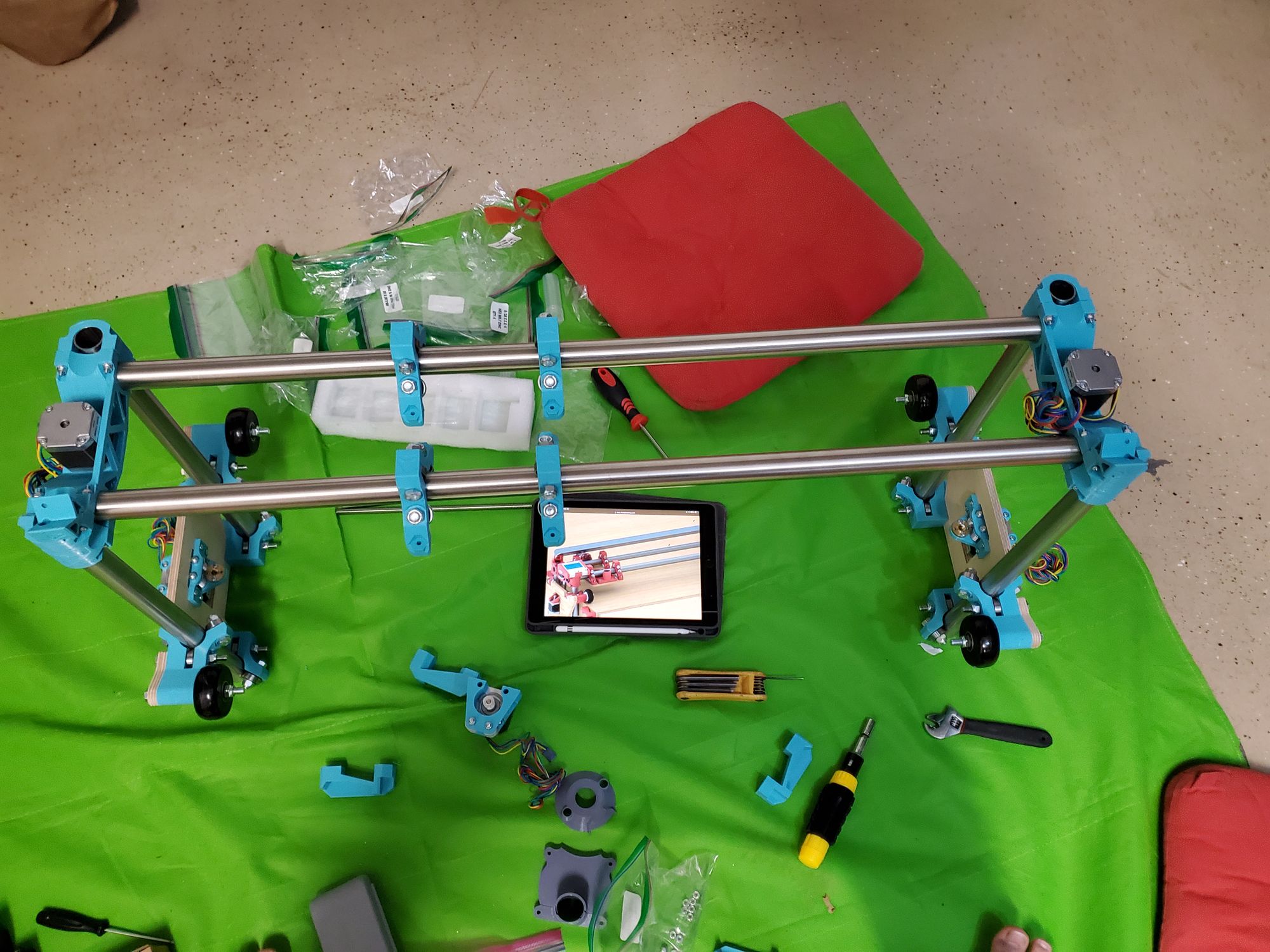
After doing this I had to add the 3rd bearing for 8 more assemblies. I couldn’t have done this earlier as this “bolt sandwich” contained: bolt-plywood- plastic-bearing-plastic -locknut. It was even harder to secure this work as I had a massive piece of plywood that I also needed hold. This ended up taking much longer than I anticipated, taking 2.5 hours rather than the expected 1.5. After this was all said and done I was finished with the side rollers and had an assembly that looked like this:
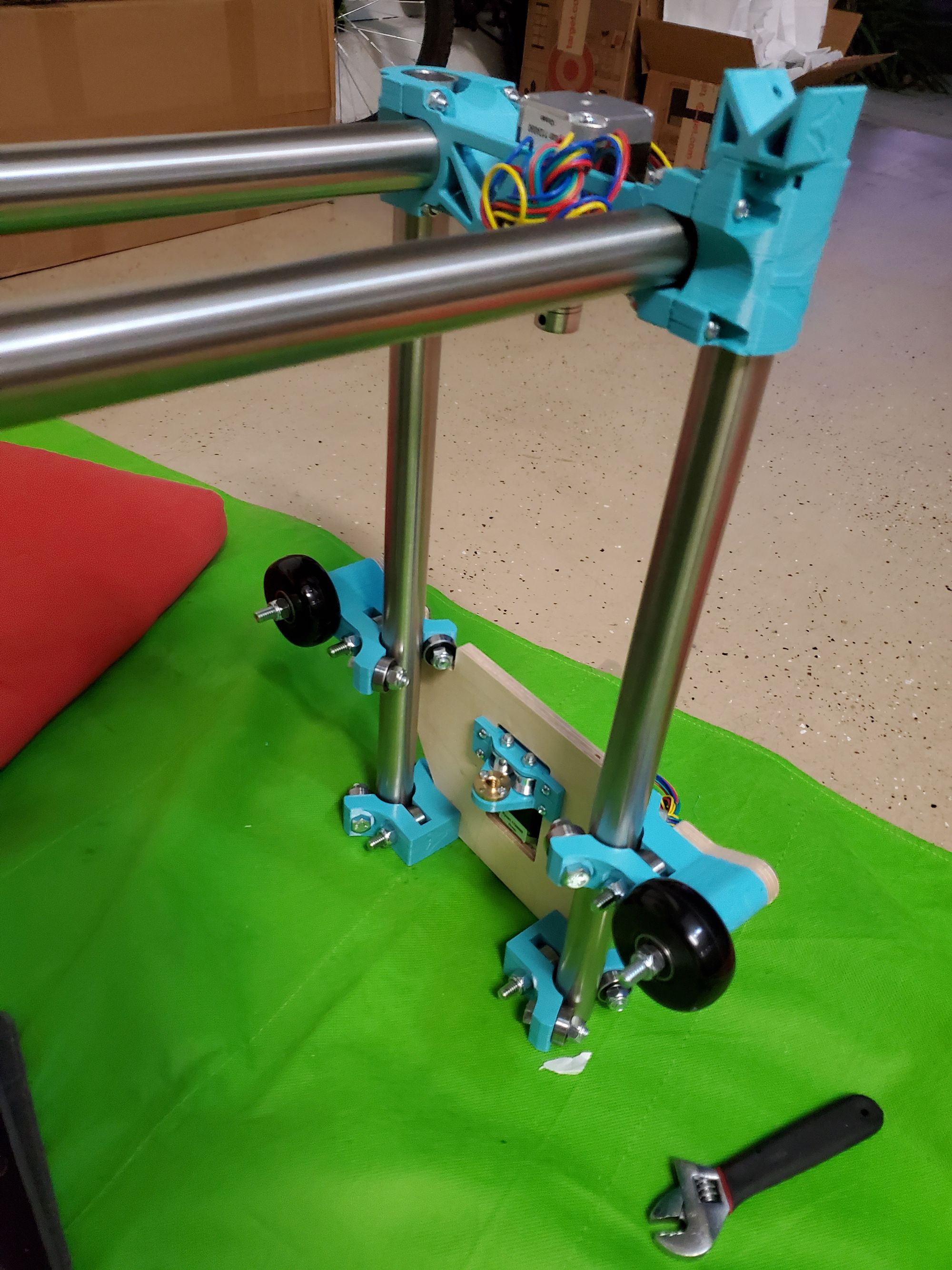
Each side roller looked like this (I haven’t put the lead screw in):
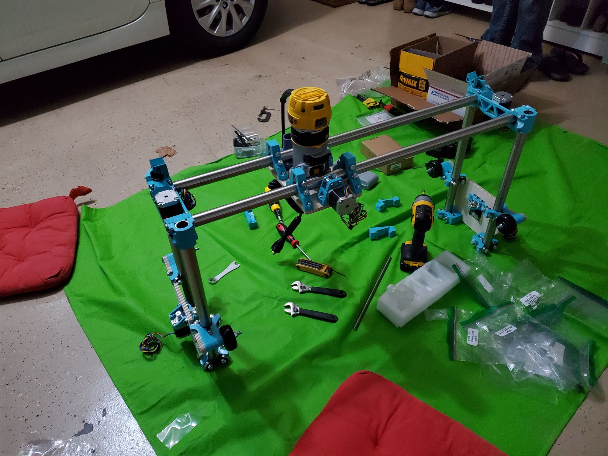
After I did all of this I had to put the center on the 4 rollers. This wasn’t as difficult as the other parts, but I was still difficult as the alignment of the holes was directly correlated with the tension on the rollers. This along with the bolts being just barely long enough gave very little room for the nut to engage. This made it much more difficult. After mounting the router and the X-axis-controlling stepper motor to the plate, which they didn’t include enough bolts for so I had to look through a pile of spare bolts until I found 4 that worked, I was ready to call it for the night, this is when I noticed my mistake. I had put the assembly 180° off. I decided to call it for the night anyways, I would work on fixing this while I am waiting for the wood glue to dry for the sled. This was my progress by the end of day 2, with the incorrectly aligned toolhead:
Day 3: 12/24
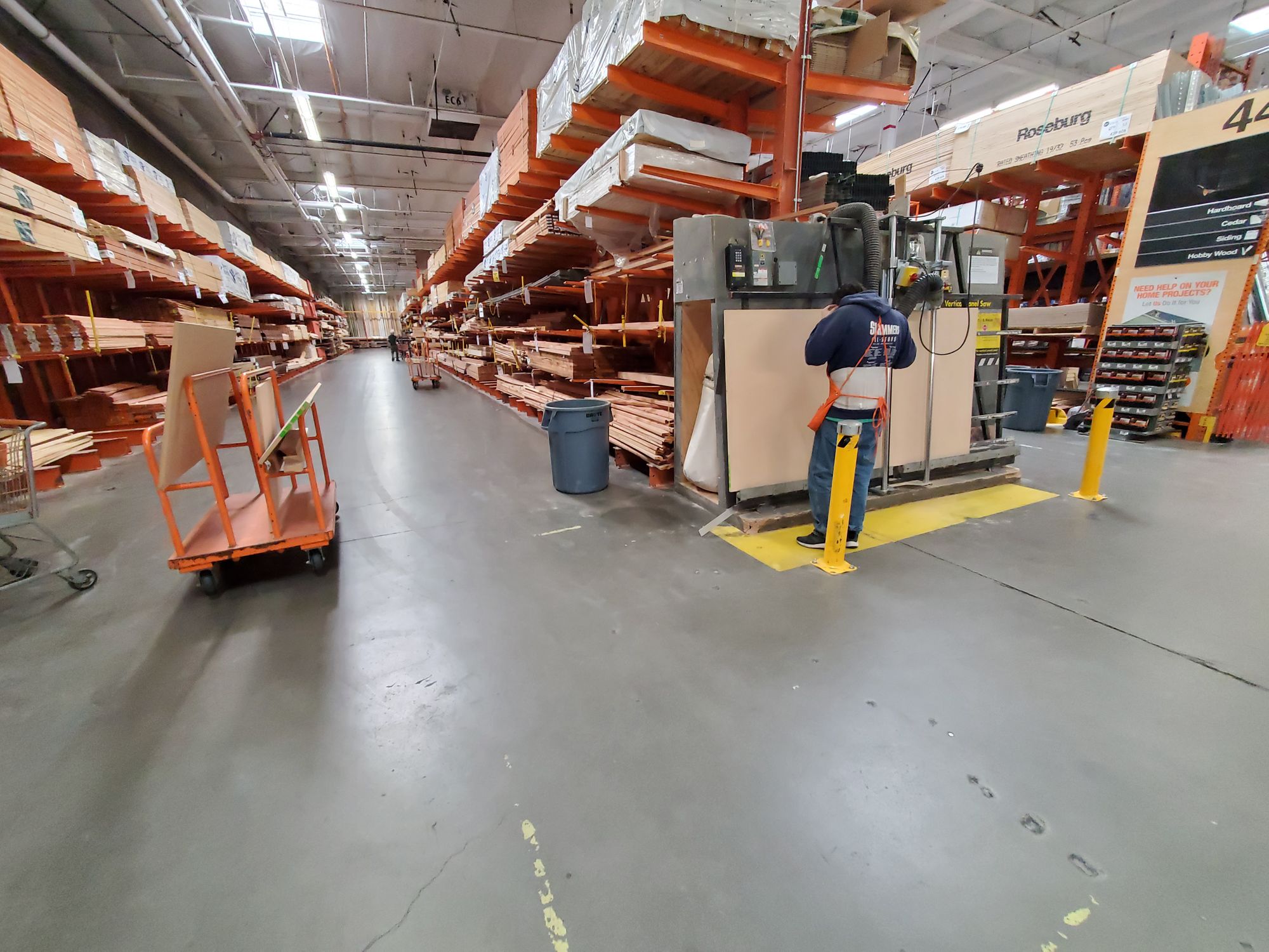
What’s the saying? There ain't’ no rest for the wicked? Well the holiday spirit isn’t going to divert my focus away from the CNC. I went to Home Depot, list in hand, to get all of the wooden pieces that I needed. After spending 2 hours cutting the wood and collecting what I needed I finally had everything. On a quick tangent, the wood cutting machine (for sheets) was really cool. It’s called a vertical panel saw and I have never saw seen anything like it. I found it really cool how it perfectly cut the wood without the normal hassles with a table saw.
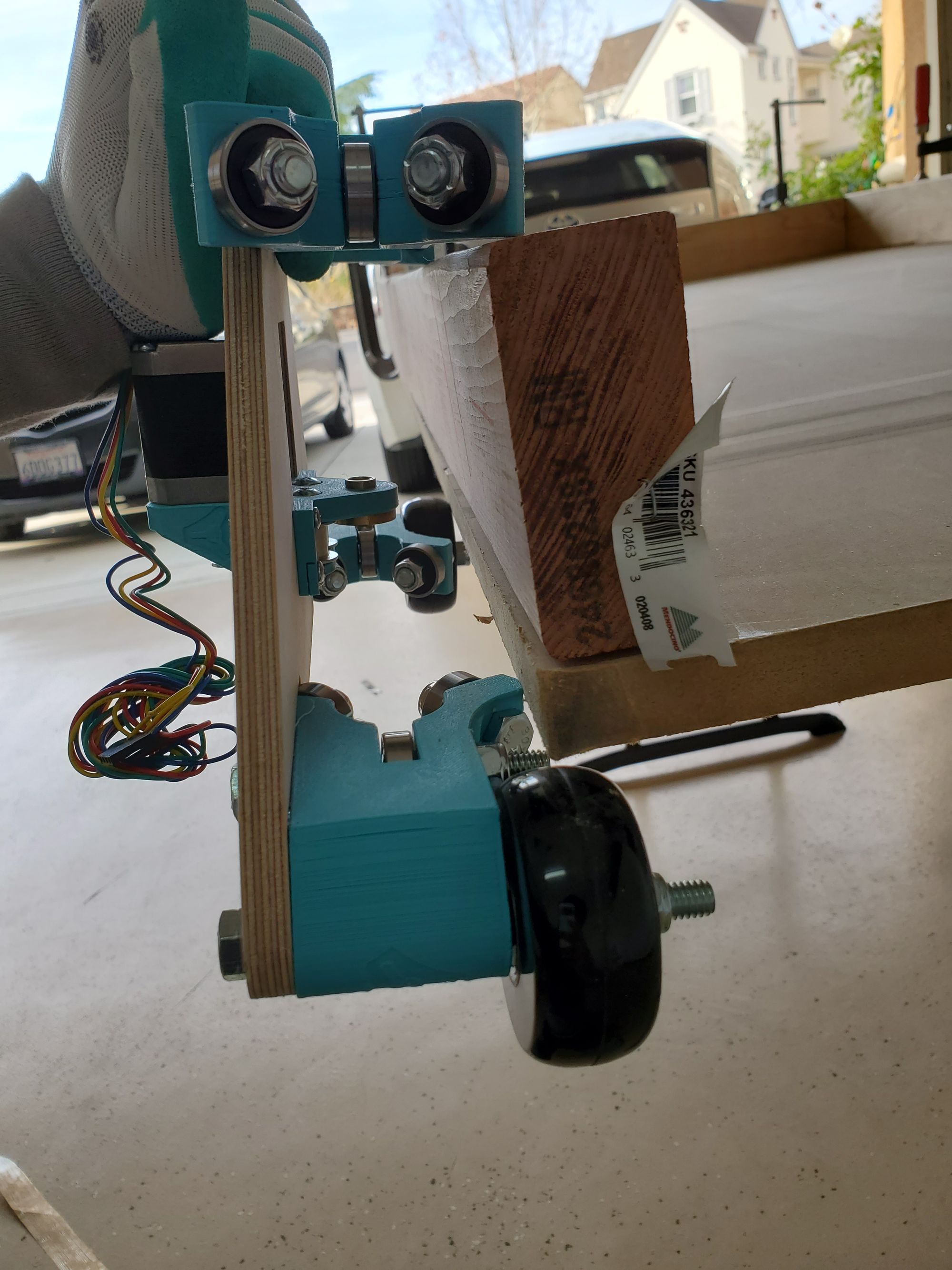
After getting the wood home—I never realized how heavy mdf is— I started clamping the wood on top of the table with the intention to start the construction of the sled. This is when I realized the huge mistake that I made. The 2x4 is actually 1.5 x 3.5, for some reason I thought this was 1.5 x 3, as a result of this the 2x4 actually interferes with the rollers. The only option that I have is to get the wood recut, which is gonna take a few days. Until then I decided to finish everything else that I can, this included fixing the direction of the toolhead carriage and cutting the metal angle that is used to mount the wires. My mistake:
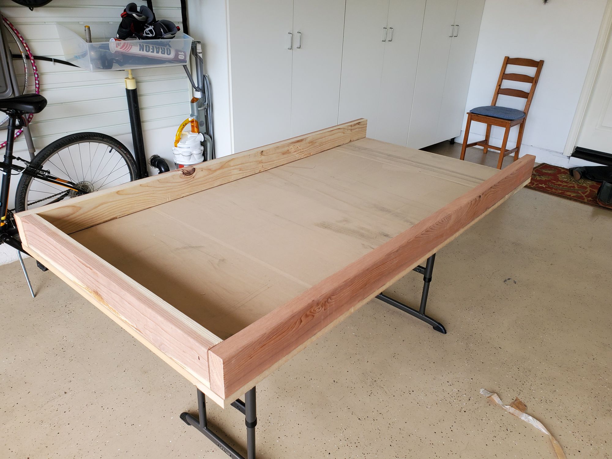
This is what the sled will look like (upside down) when it’s completed:
Day 4: 12/29
Oh how I missed working on the CNC. I spent some time (I think partially the day before) fixing the center carriage which was flipped 180 degrees, this took about 20 min and after this was done I had to sort out the situation with the wood. I was initially planning on going back to home depot either to : a. Get an inch cut of the width of the wood or b. Buy smaller wood and get that cut to size; Luckily I had to do neither. One of my close friends' dad, who lives technically next door (there are a bunch of houses, but they are on another street), was able to cut the wood for me. We used a skill saw on the back of his truck bed and a few clamps. It made a huge mess, but in the end I was able to cut off an inch from the end. The cuts even looked half decent! After getting a splinter (or 4) getting the wood back home, I sanded the rough parts down and prepped it for assembly.
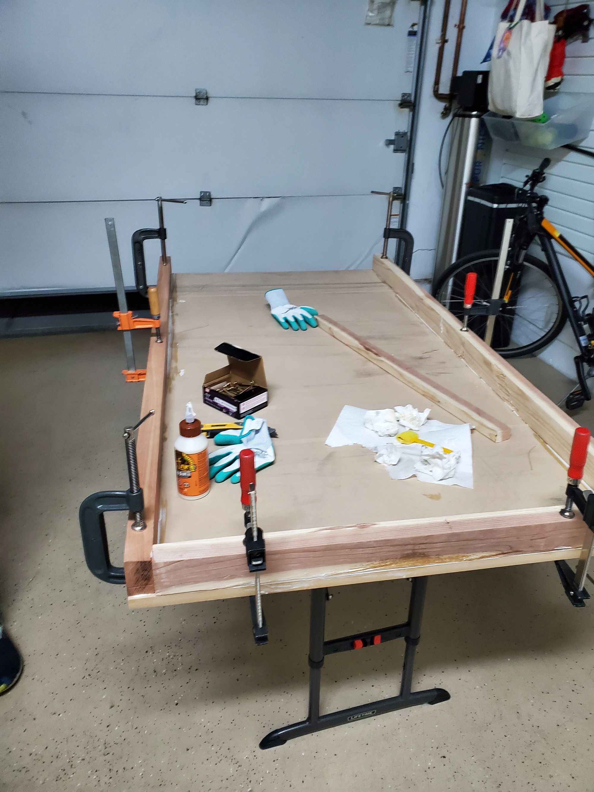
I called my good friend over and we worked together, socially distance and with masks, on the glue up and wood screw up. We first put the wood roughly where it was supposed to go. After getting one of my sister’s art brushes (sorry!) I had all the tools for the initial glue up. For the initial glue up, we basically moved the 2x4 (now missing an inch, so 2x3?) 1.5 in. to the left (the 2 is actually 1.5) and then with this slit of mdf we put the glue, we then put more glue on the 2x3 (that sounds unnatural) and then mated the glued up surfaces together. After applying a metric ton of clamps (insert clamp champ meme here), we started drilling holes. The drill bit burned me a few times (it got over 200 degrees fahrenheit!) and after wearing a pair of gloves I was able to drill out the remaining holes. You may be asking, why do I need to touch the drill bit? Good question, for some reason, the bit keeps on falling out of the drill—and yes I have tightened it real good.
The glue up (missing clamps):
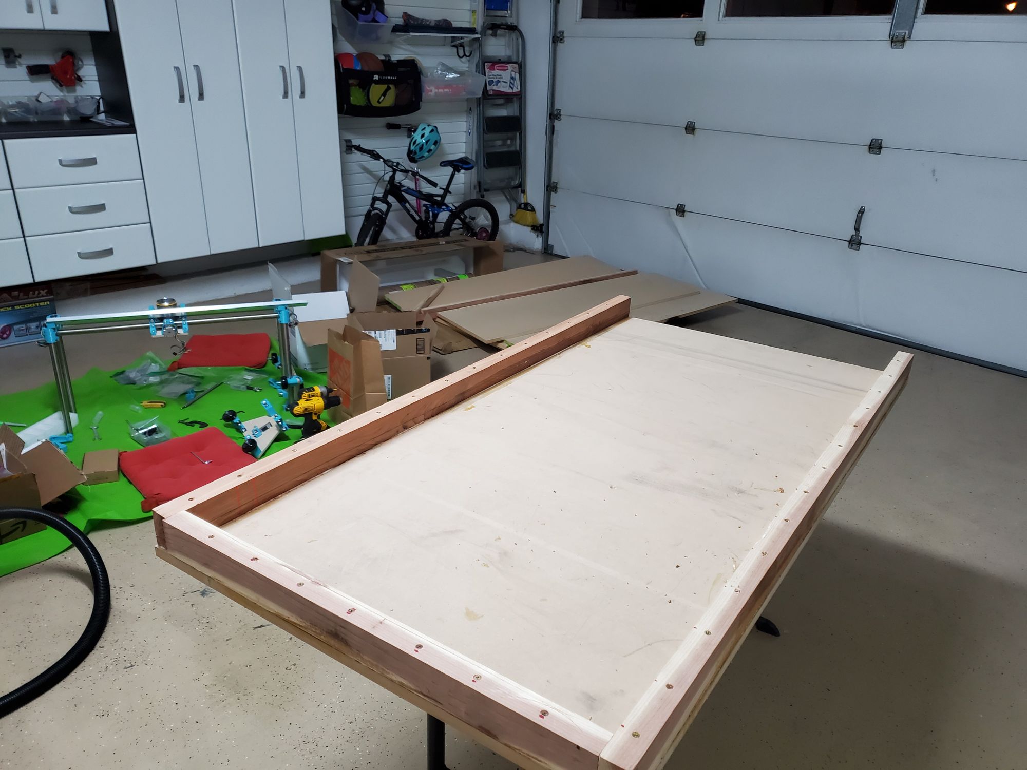
We may have gone overboard (pun intended) making 14 holes (on each side!) rather than the needed 6, but shrug. After screwing everything in, and removing all the clamps I had a sled that was ready to be used, just not in the snow. This was by far the messiest part of the whole build and I also enjoyed it the most. The other parts of the build felt almost monotonous, don’t get me wrong, I loved listening to Daft Punk (the first website I made for fun; the link) and tightening bolts for 10+ hours, but this is slightly more fun. After putting everything in, there was one spot where the 2x4 (2x3 whatever, I give up) was pretty mangled and sharp (from factory). I didn’t think of a better solution and ended up following what my dad suggested, put a thick layer of wood glue and let it harden, if there is any annoying glue, sand it down. I did it and can’t really do anything else until that is dry. I took a few new photos, here:
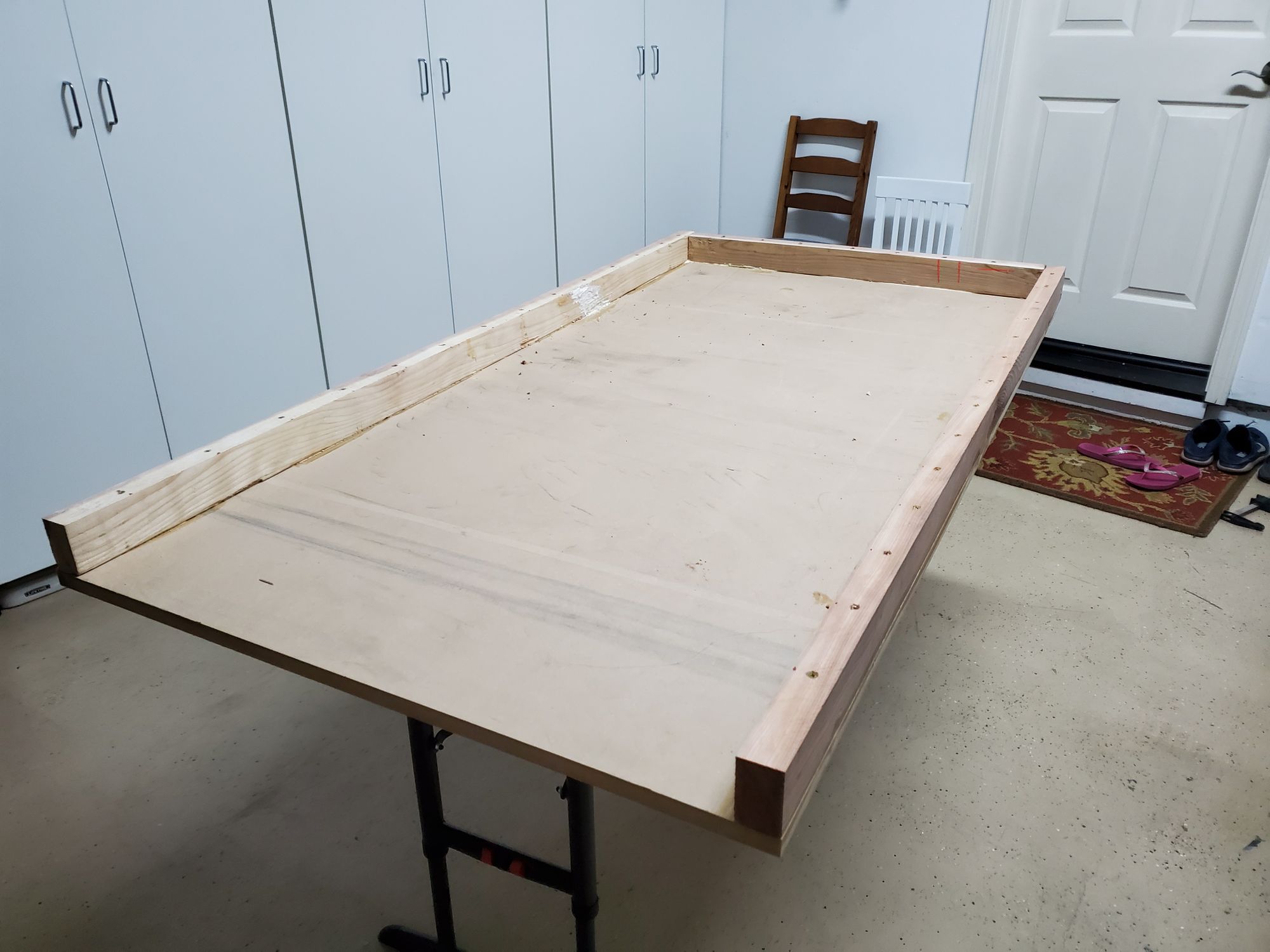
You can see the path of wood glue on the left side near the back.
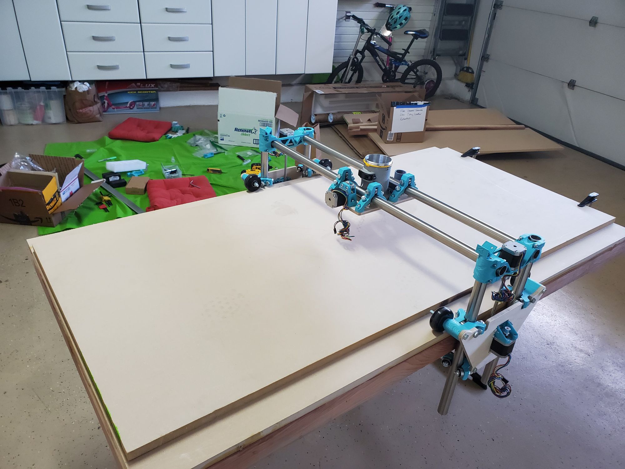
CNC and the table. 👀. Oh yeah, it's all coming together!
Day 5: 12/30
One more day until this sorry excuse for a year can come to close. Man, I hope 2020 wasn’t a warm-up for 2021. Anyways, the CNC is now kinematically ready!
After vacuuming any excess sawdust or dried glue, I flipped the sled around and onto the comically small table. I then cleaned off the top surface to remove any lingering particles. After that I put the stock that will eventually become the spoilboard onto the wooden piece. This stock had a few knicks in it so I used some left over mdf sawdust and wood glue to fill it up. Then I took the spoilboard and centered it on the board. This gave me the sled, fully operational.
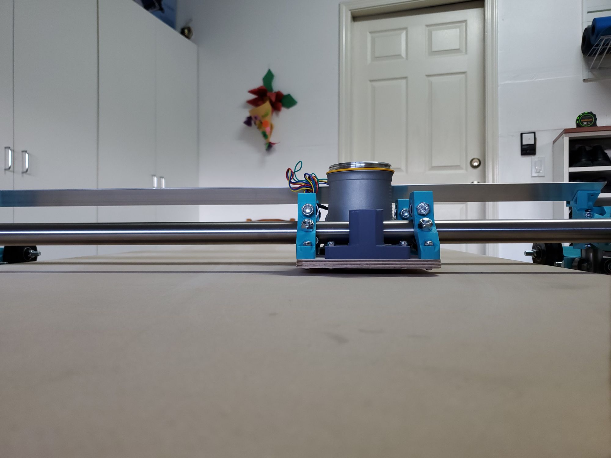
The Lowrider CNC was now ready to be mounted on the sled, I was really nervous, what if I had miscalculated by an inch or so, it has happened before. I decided to attach the z-rods and then took the entire assembly and put it on the table. I first panicked when I tried to put the CNC from the top and then realized that there was no way that this would have worked. After sliding the CNC from the side everything....worked out! I was relieved. The only minor issue was that in certain places, the Y-axis movement was not perfectly smooth, however this is probably just b/c the machine hasn’t been fully squared yet. After this I tested the X, Y, and Z motion, all of which worked perfectly. Then I lowered the gantry to the lowest position and started looking for flat spots or irregularities. Besides, the one I found earlier, I didn’t find any others.
I placed the router in and thought a little bit about how I would manage the cabling. I decided that the router would probably be plugged into a ceiling outlet while the machine would probably be plugged into any other outlet. I also contemplated adding integrated wiring, but realized that is something that I would do later.
I am so relieved that this part worked and can’t wait to begin the wiring, I’ll probably end up asking my friend who already built his on how to cable manage the CNC. Here are a few shots and videos that showcase the kinematics in action!
View from the table height:
Day 6: 1/8
Welp, it's been a whole year since I’ve worked on this, damn time goes by quickly... With the junior year crunch starting, I’m getting less and less time to work on the CNC, but you know what, I said I'm gonna do it, so I am. Also happy new year. Hope 2021 is better than 2020 (Dre and Capital Insurrection 🤔)
Before I can work on wiring up the stepper motors and etc I first have to attach and tension the belts. Future Vedansh here, skip the next paragraph if you want to avoid my rant about why electronics look ugly*.
In my (mechanically minded) opinion, electronics ruin the looks of the machine (*if not done properly). Most of the machines that I have seen and have worked on are mechanically focused and have little thought given to the electronics — a infamous saying during robotics design reviews is: “Electronics will figure something out”. As a result, most designs don't actually try to conceal the wiring and more often then not, the smooth powder coat and painted accents don’t look as good after everything has been plugged in. My goal has always been to try and make my mechanical design as easy as possible for anyone who is (unfortunate enough to be) working with me, so that they can perform their best. Since I am doing basically all the mechanical and electrical work, I thought I may as well make the wiring look as clean as possible.
Anyways, the belts add character to the machine, unlike most (but not my) electronics (see my rant above, if you skipped).
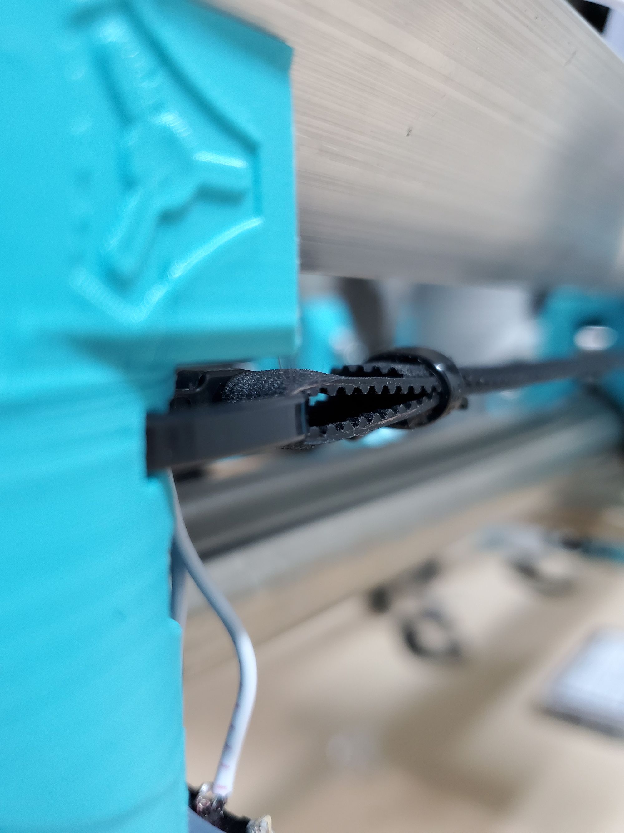
To attach the belts I first created a loop on the belt spool, this took a bit of finesse and I omitted a 3D printed spacer because it serves little purpose. After attaching the belt with a zip-tie (I started with the x-axis) to one side, I realized the mistake I made. The large spool won’t fit through the ~5 mm opening that serves to attach the belt to the pulley. I had to cut off the section that I just made and I first spent 10 min trying to put the belt through the pulley— at least a friend came over and helped tremendously with getting everything to go in.
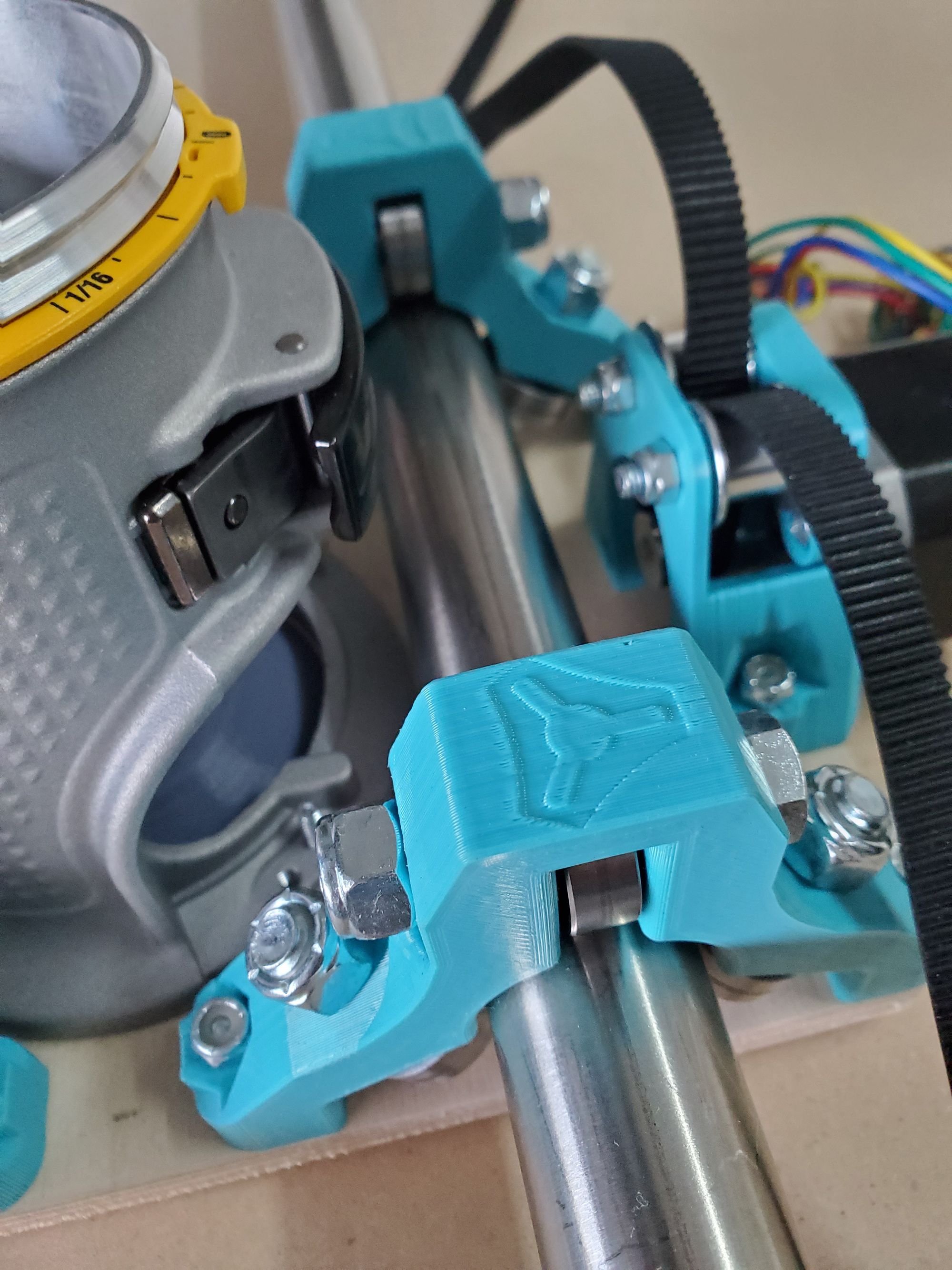
The tight hole the belt needs to be threaded through.
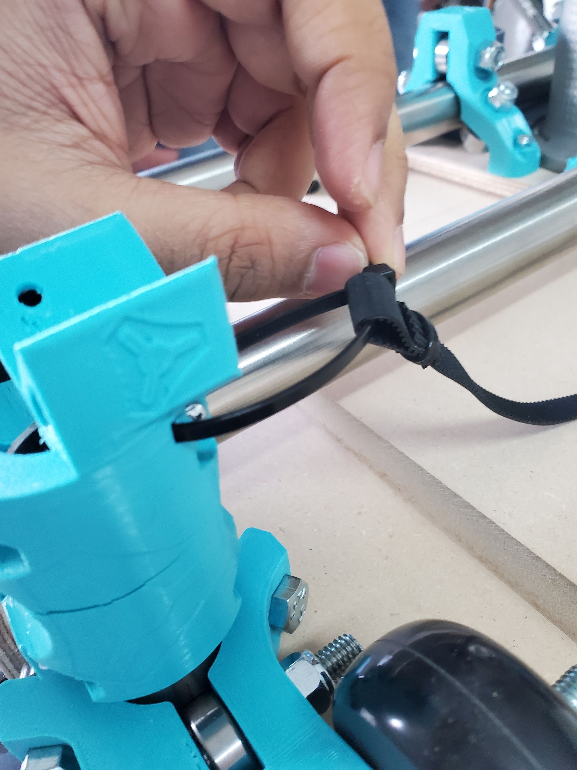
What the loop looks like.
After redoing the loop, cutting the belt to size (if I cut at the end of the axis, it's just long enough), adding another loop, and tensioning the belt, I was finished with the X-axis. This is what the CNC now looks like from a top view!
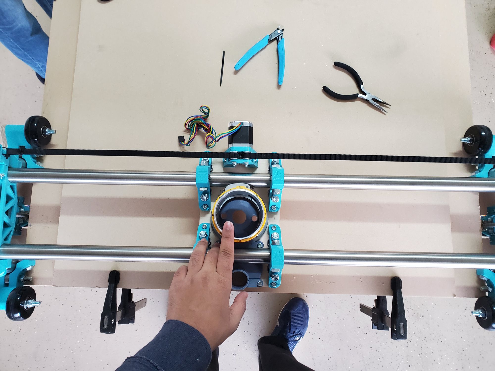
Here is a video of the kinematics with the belt. The belt stays stationary, the motor moves.
After completing the X-axis, I started work on the Y-axis, specifically both of the rails. This CNC has 2 Y-axes. I call them Y1 (or Y left) and Y2 (or Y right). To attach the belts, we need to attach the anchors to the table. This is also what the machine uses to self-square. I started by aligning the 3D printed part to the edge of the table then drilling the holes. This took a bit of trial and error (though the error was mostly me just not feeling confident), but eventually I drilled the holes for one of the pieces.
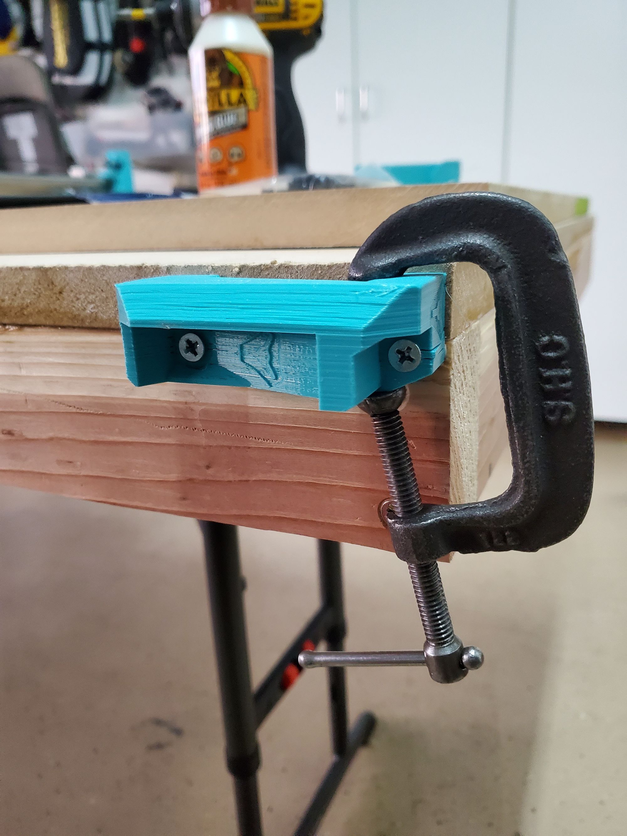
In a rush to try and move on the other side, I used an impact driver to put the screws in. This was a huge mistake. Since I was using a countersunk head screw with a non-countersunk plastic piece, there was a point of high stress, and since I forgot to stop right before I hit the plastic, the piece cracked. Shit. I was frustrated that I was gonna need to print another of this model, but then it occurred to me, this piece is gonna be experiencing little if any stress. So I just chucked a clamp on the piece to prevent the print from splitting any more and decided to manually tighten it with a good ol’ fashioned screwdriver. This is how it looked:
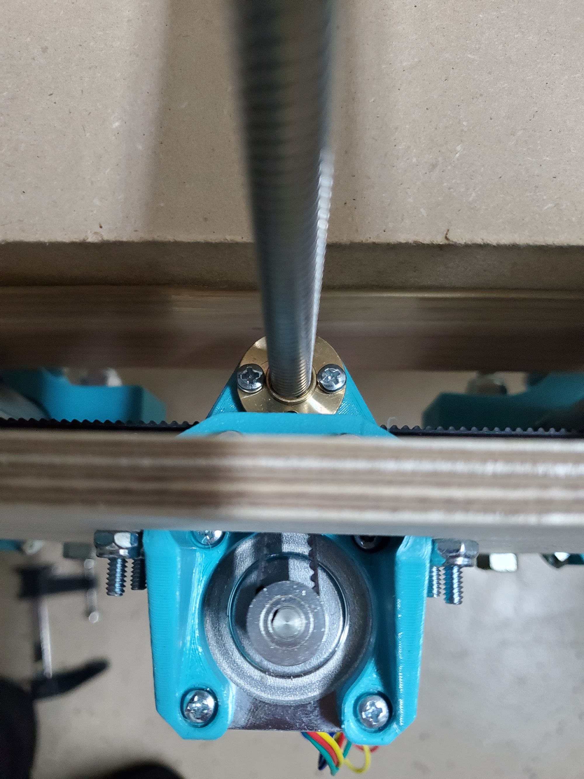
I did the same thing on the other side. Just to make sure that this didn’t loosen over time, I coated each screw in a thin layer of wood glue, this would hopefully add a little bit of strength and fill in any gaps, mostly the one between the wood and the plastic, reducing the destructive potential of potential weak points. I then added the belt, this time threading it through the, somehow even more tight, y-axis. This is the crazy path we needed to push the belt though:
I attached the zip ties and repeated this for the other side.
The Y-axis (oooo, cool angle):
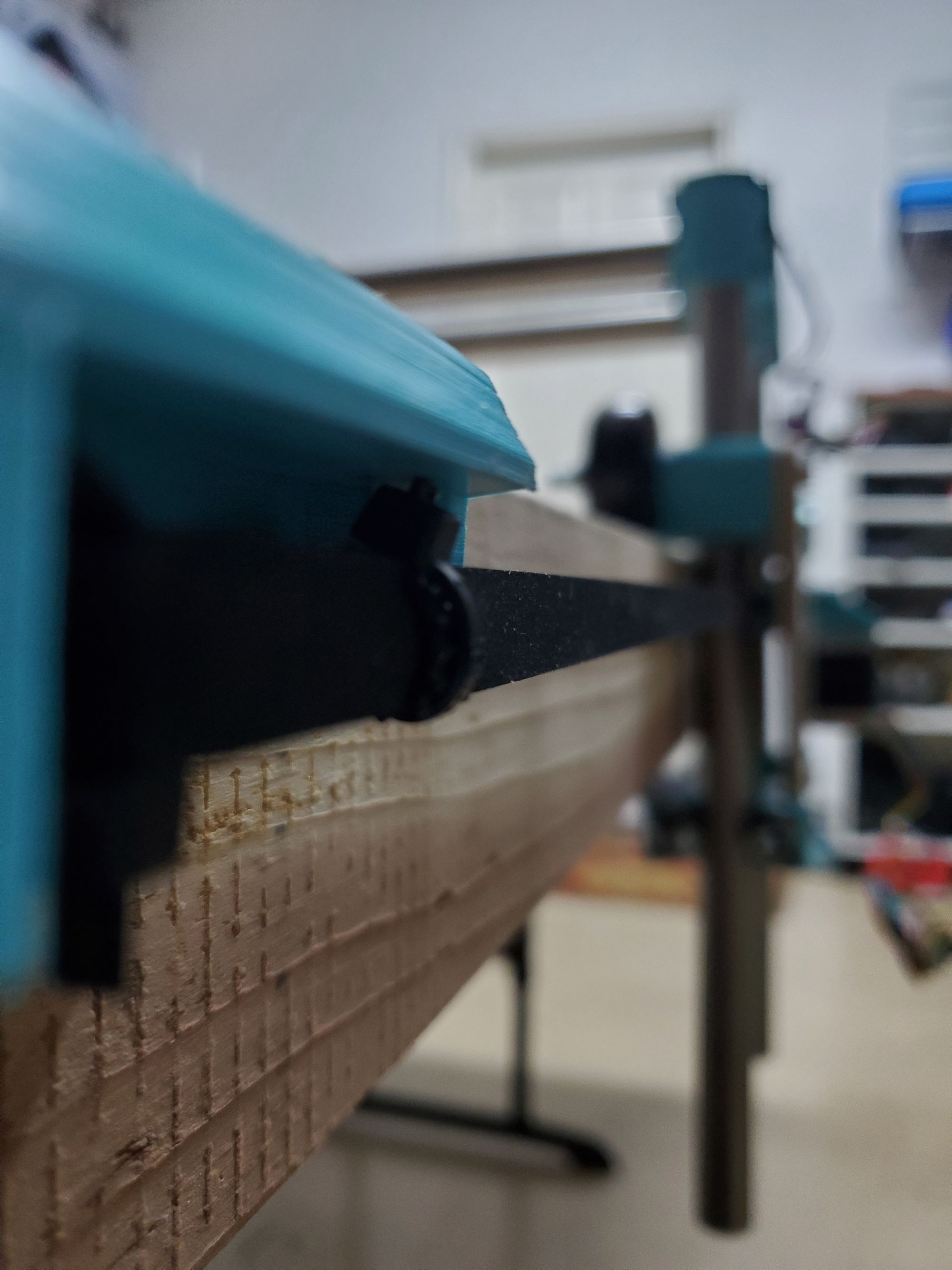
I thought I’d be able to continue with the electronics, but unfortunately I had to wait for mounting hardware, in the meanwhile, I disassembled the CNC (I just removed the carriage from the Z-axis (which uses lead screws rather than belts). This left me with an assembly that looks like this:
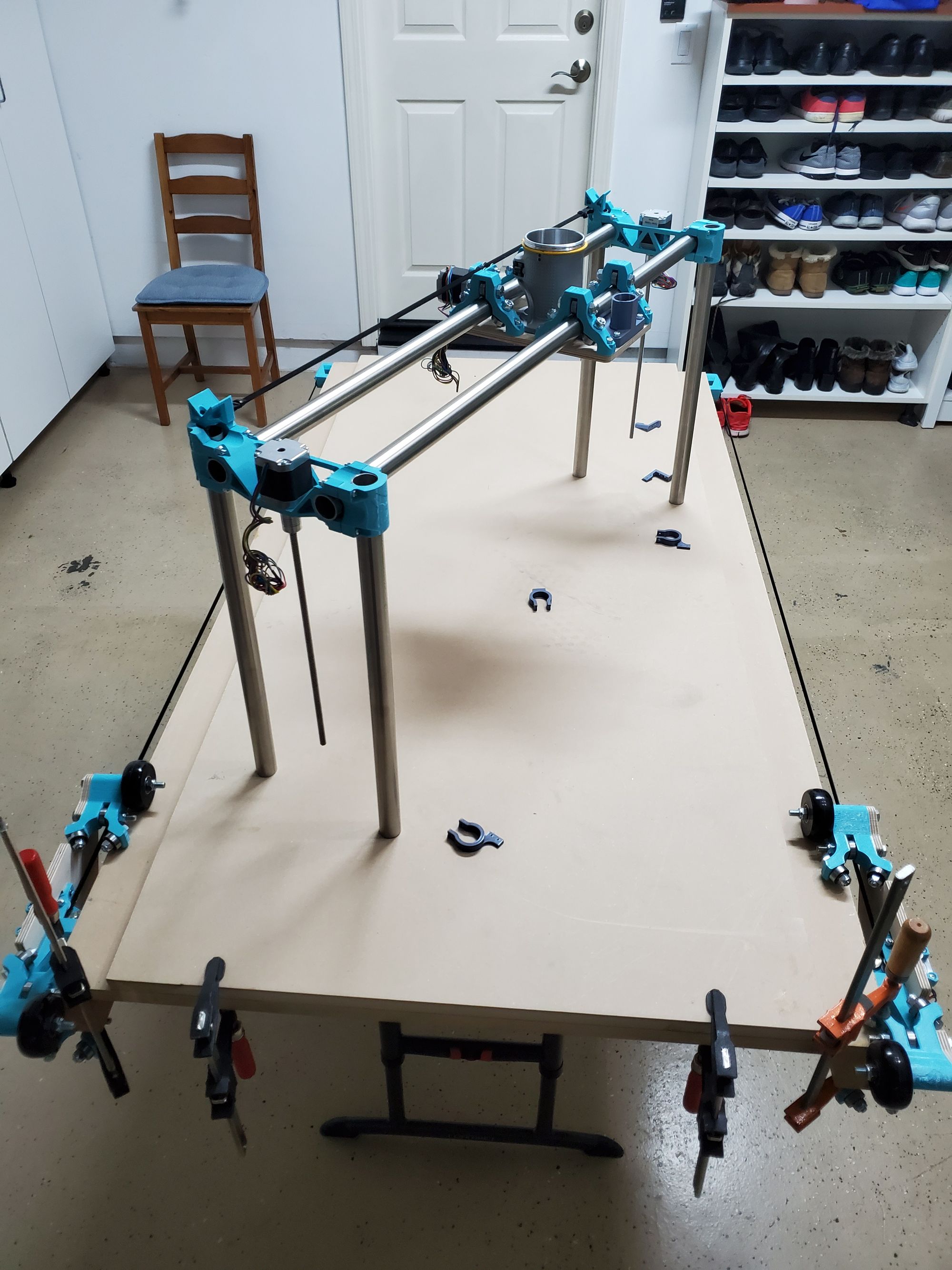
Day 7: 1/13
After 6 days of working on the mechanical portion of the CNC, it’s quite relieving to be working on something else. I am a mechanical engineer by experience and electronics is definitely not my strong suit, which is precisely why I am really excited about wiring everything up. I believe that I can make the electronics look really well integrated into the overall CNC, hopefully by creating modifications to the design to accommodate such changes.
I found some of the mounting hardware that I needed and was ready to start attaching the mounts for the limit switches. These mounts need to be attached to the wooden side panels, but on the inside. I sort of forgot about this step while assembling the CNC which is why I had to partially disassemble it. I also have to clamp the Y axis (the wooden assembly) to the frame in an unusual way just to gain access to the place where I want to put the limit switch.
I drilled out the mounting spot for the y limit switch, which I did in a VERY jank way. I wasn’t able to get the precise hole location as the large 3D printed pieces prevented my drill from even starting the hole. I contemplated my choices. The only logical option that I could think of was to print something like this. This is a handheld manual drill that while slow, may allow me to accurately drill the holes from the inside rather than the outside.
I decided to YOLO it, but I did so with a strategy in mind. The hole size that I needed was around 2mm. I had a bunch of ~1/2 mm bits— these are the ones that break if you look at them. I started off by trying to visually place the holes, using calipers and ensuring alignment from the x and y axis. After doing this I drilled the first hole. This was pretty much bang on. With the location of the second hole now clear I drilled the second hole. Then I put the piece and looked at the alignment. There was a slight shift on one of them, so I simply drilled another hole w/ the fragile bit and after a bit of time I was finally able to get the tiny holes roughly aligned. Then I took the larger bit and made the holes bigger. This— admittedly convoluted— method worked much better than I thought it would.
After finishing this step I started to plan the rest of my wiring. I needed to understand where each of the wires go and to do this, I put each wire in the roughly right spot. This way, I had a better idea of where each wire goes. I spent about 30 min just deciding how I would run the cables and after that I started putting the wires in their rough locations. This is what the table looked like at this stage.
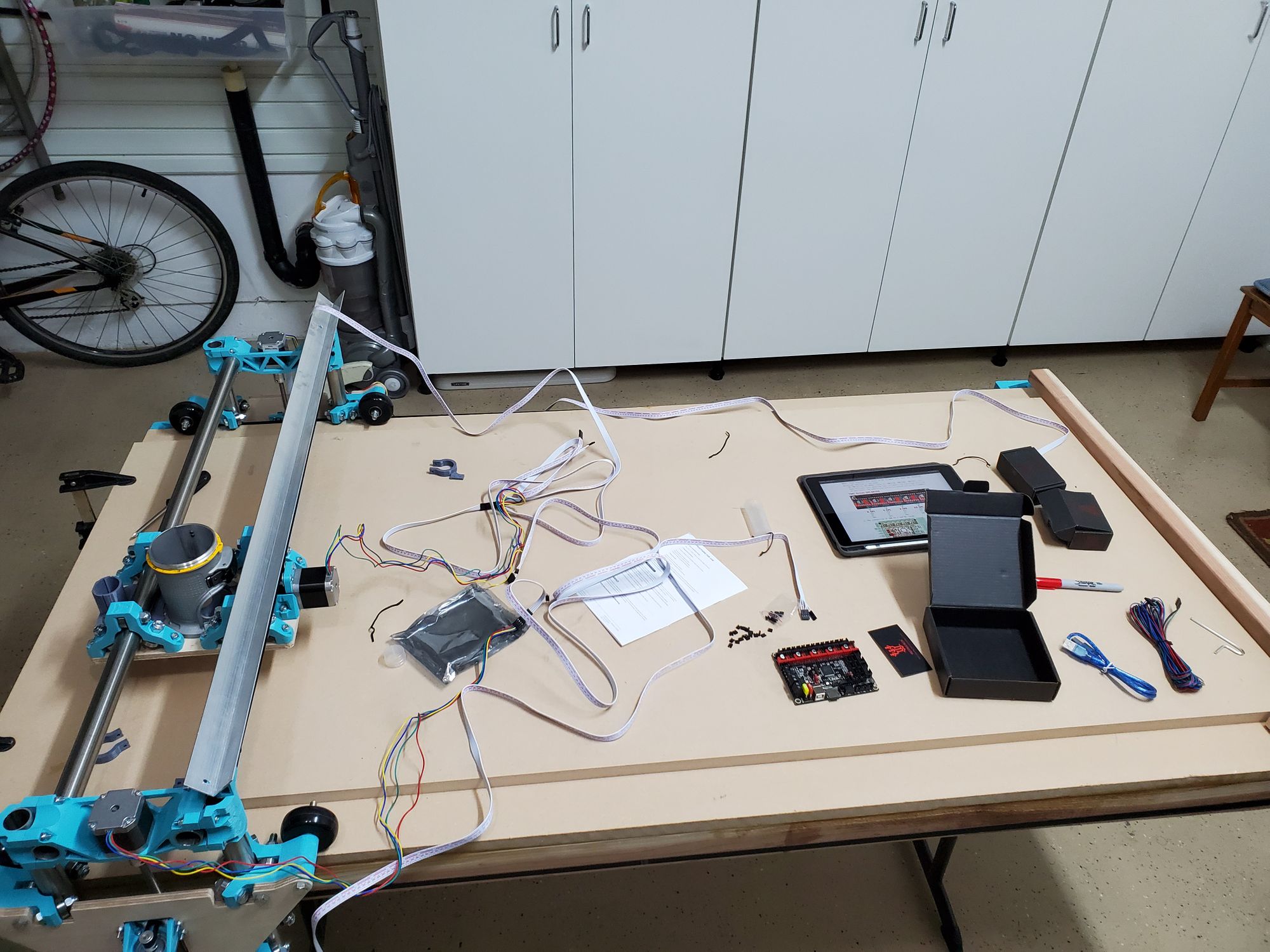
After this I started to focus on the electronics. I went through half the internet trying to find a wiring diagram for the motherboard, and there really wasn’t a reliable one. I decided to read through the manufacturers schematics and try to interpret where each of the jumpers go. These jumpers are physical connections that I need to make on the motherboard in order to ensure that all the electrical pathways are solid. Once I was confident in what I had, I simply had to do the electrical connections. After doing that, I put the stepper motor drivers in their spots and put the heatsinks on the drivers. Here is an image of the finished board.
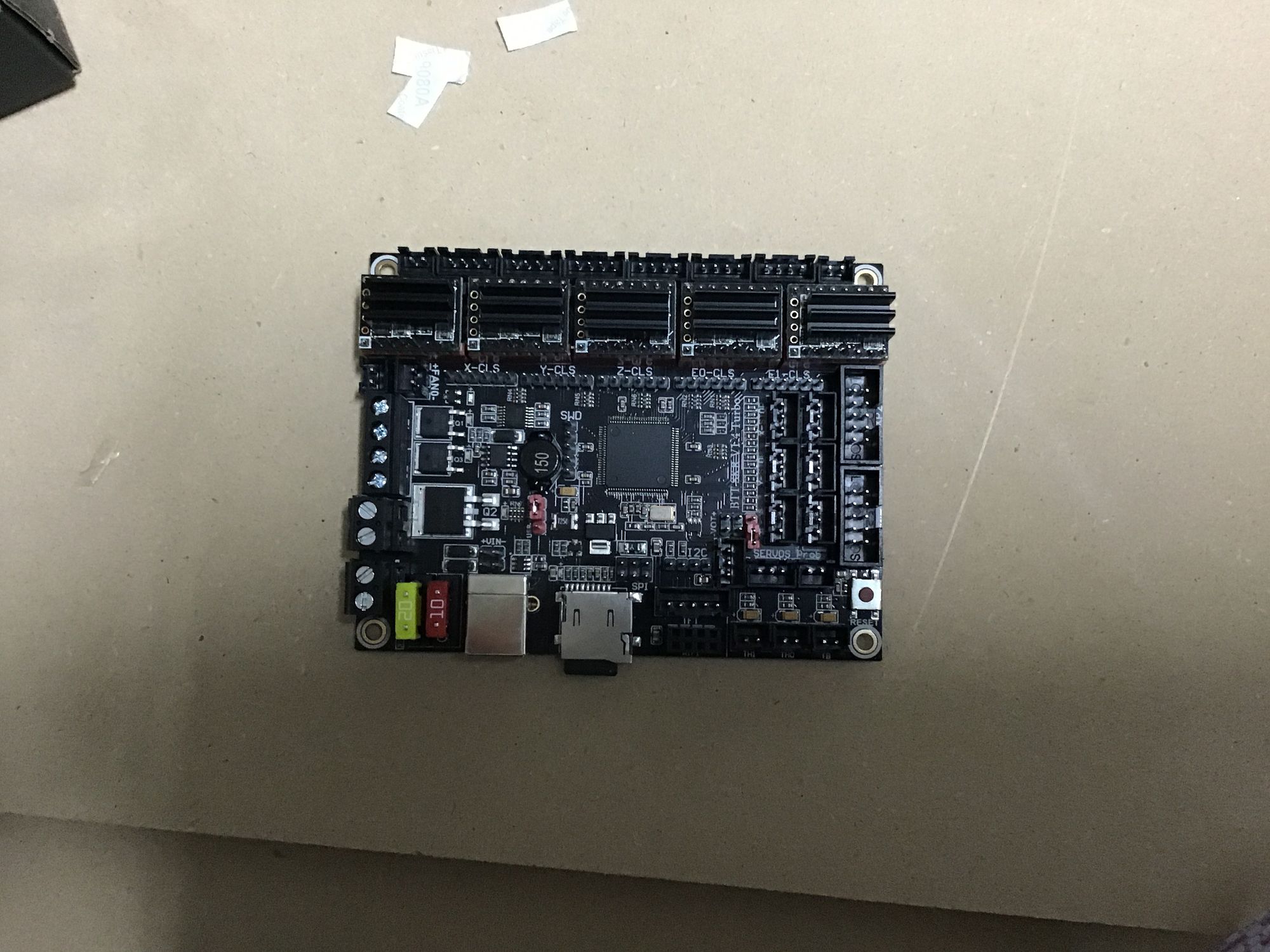
The next step was to start wiring everything up, and in order to do that I decided that I should first solder all wires to the limit switches, then mount the limit switches. I asked my neighbor of his soldering iron and my anticipation grew.
Day 8: 1/14-15
Sheesh! Today was a productive day!
In the morning I received all of the mounting hardware for the CNC that I needed. This was 2 boxes of nuts and bolts needed for mounting many miscellaneous things. The funny thing about the box I bought was the pricing scheme. I really only needed a few M3, a few M2, and a couple of nuts for each, instinctively I went to McMasterCarr to look for the nuts and bolts that I needed. I realized that it would take a few days to get here (closer to 5, and keep in mind this happened on the 11th or so) and I felt as if the price was a little bit high, sure enough I was right. I went onto Amazon and found these two boxes for about the same price, but containing more than 10 times the variety and number of bolts— they were a little bit weaker, but for this use case it really doesn’t matter. (Yes I used photoshop to remove the label information, nice try)
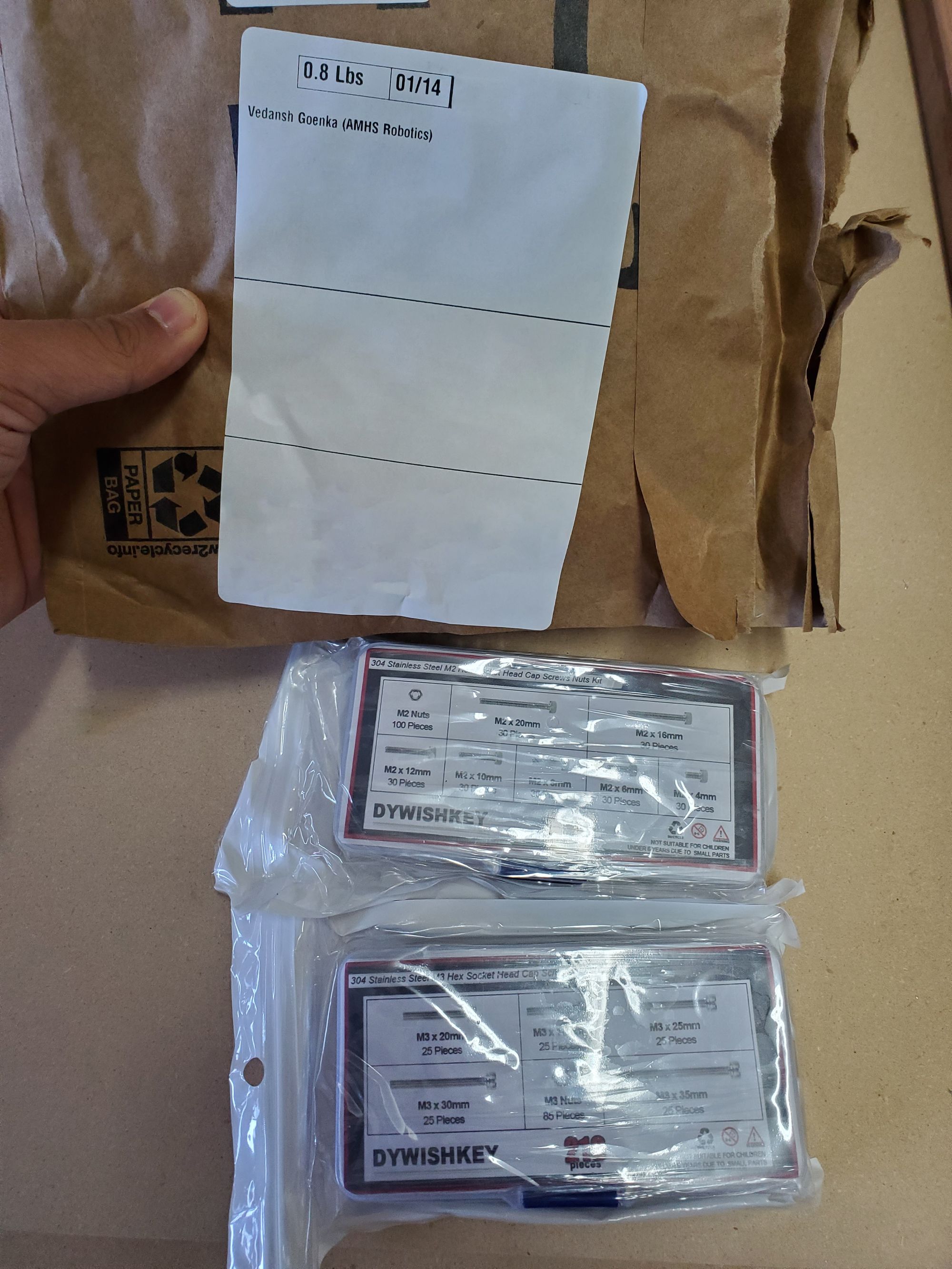
I borrowed the soldering iron from my cousin who lives next door— I thought this was gonna be a piece of cake, boy how I was wrong. I’ve used his soldering iron before, and since neither of us solder that much, it's one of the cheapest soldering irons out there. As a result of build up on the soldering iron tip, there was only one small spot which contained enough heat to actually melt the solder. What made this much harder is the fact that the soldering must be done on the CNC, as the cables are looped through holes. If the soldering is not done on the machine, it is impossible to put the cables through the cable management holes.
This led me to do one of the most crazy, but also comical things that I have done on this project. While the soldering iron would be heating up, I would be wiring the limit switches and somehow clamping it down (I also didn’t have any clamps that were able to do the job 🤣). After that was done, I would make sure everything was in order, dash to the soldering iron, unplug it, then solder one hole. If I got lucky, I would have enough heat for 2 holes. What made this even harder was that there was only one tiny crevice where the soldering iron actually allowed the solder to melt, everywhere else, the temperature wasn’t nearly high enough. I spent the next few hours soldering 10 holes.
What made this even better was the fact that I was soldering the WRONG HOLES. Through what can only be described as a massive hole in the documentation and an oversight on my part, it turns out that I had wired the limit switch to be normally open. This means that the switch will have current always flowing through it and when the switch is pressed, the current flow will stop. This is not really the best solution for the long run. I need to basically resolve each of the limit switches— talk about a waste of time!
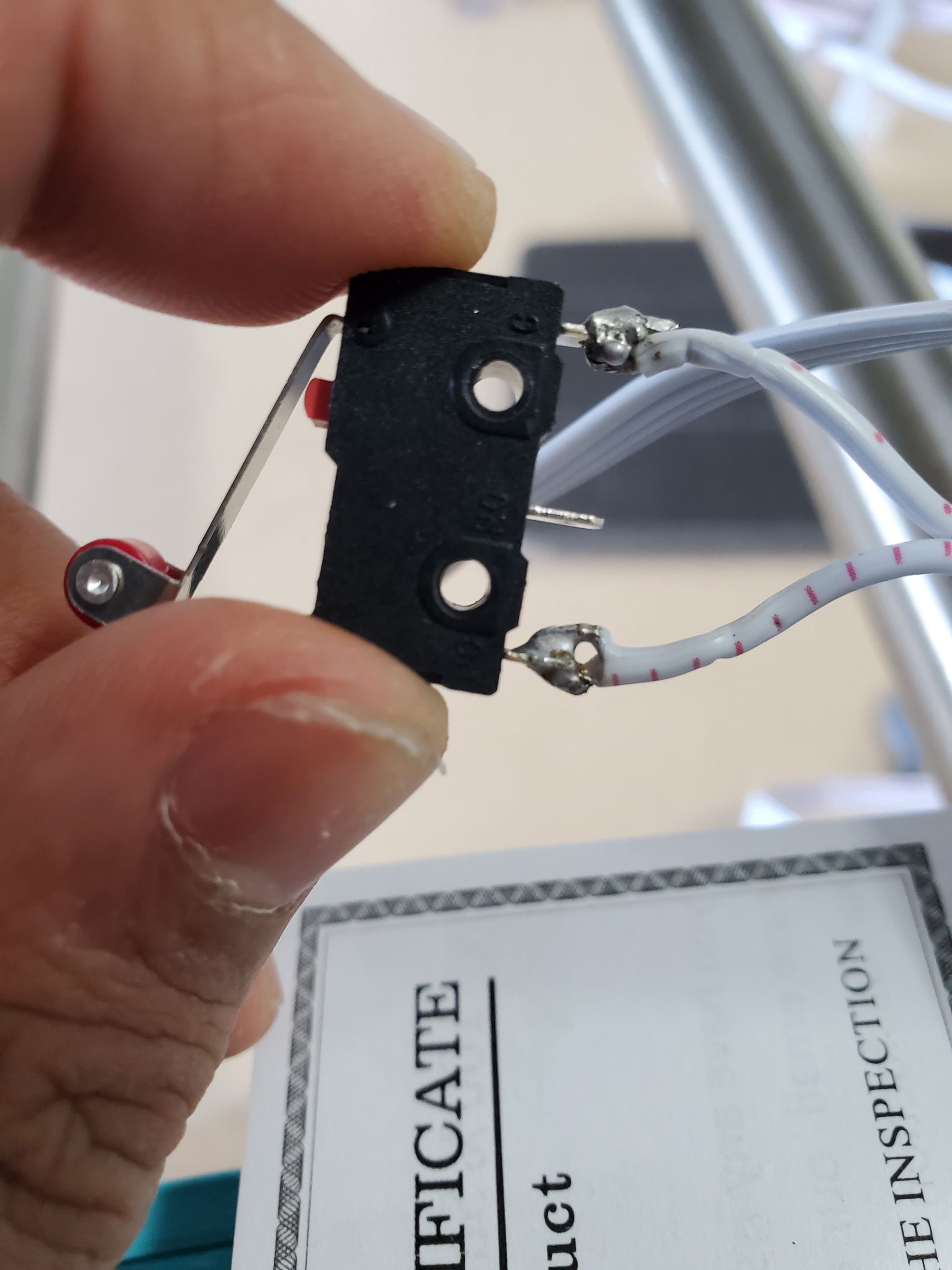
After spending another hour or so resoldering each of the holes, which at this point felt agonizing because the soldering iron seemed to become even less and less cooperative, I was finally finished. I then had to screw the limit switches in. For 3 of the limit switches, I could simply find a surface on the CNC, I used the back of the Z axis stepper motor, to rest the pieces and comfortably tighten it up. The cables had slack so I could easily pull a few inches. This only really worked for the X and Z axis, which when done ended up looking like this.
This is the Z axis switch, the cable goes to a hole in the aluminum channel, allowing it to be very neatly organized.
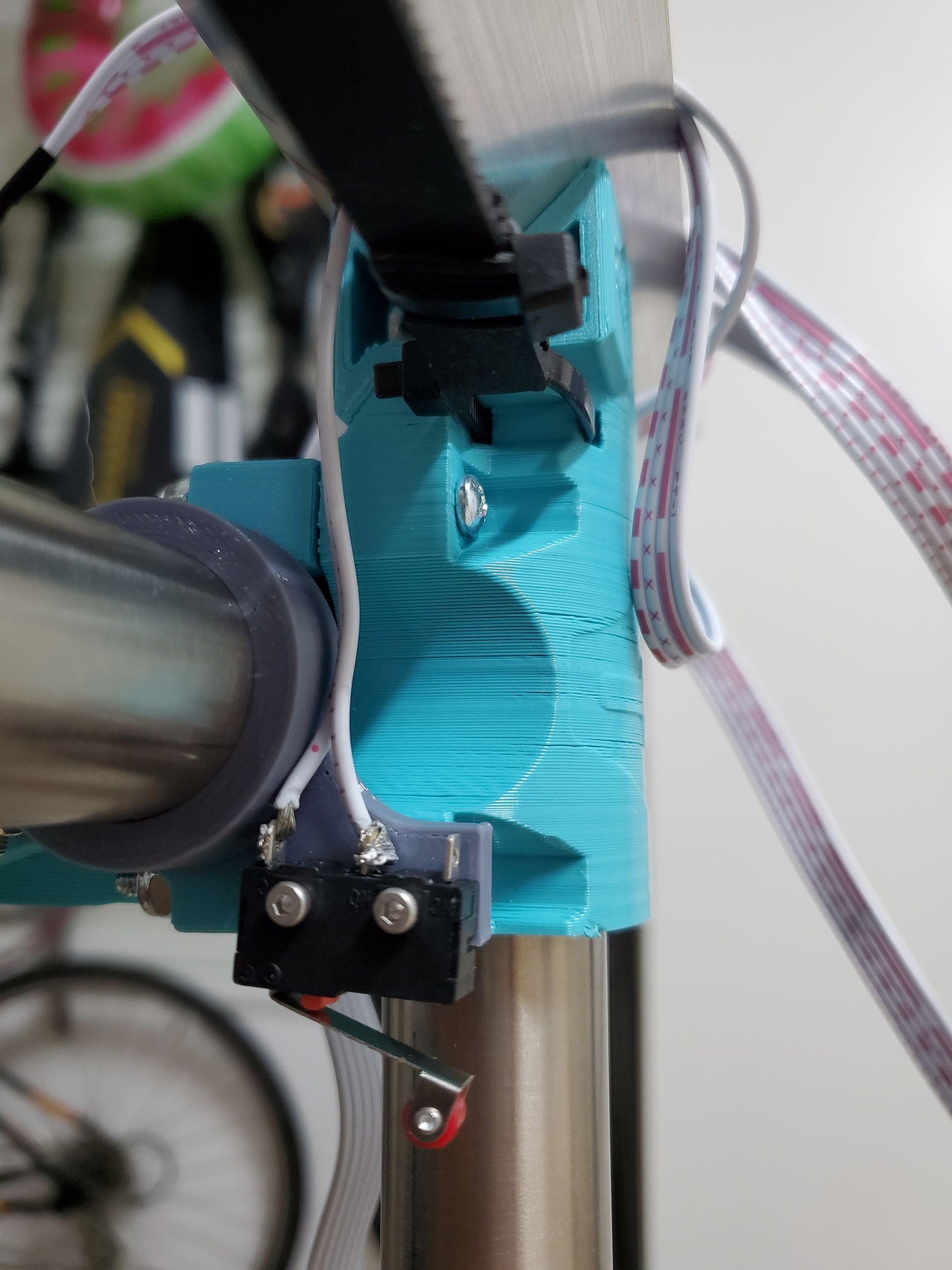
This is the X-axis limit switch, the cable didn’t really have a logical path to go through so I put it like this. Also this was the last switch that I made, meaning that the soldering iron was basically toast; I used blue tape, in lieu of electrical tape, to create a makeshift stress relief.
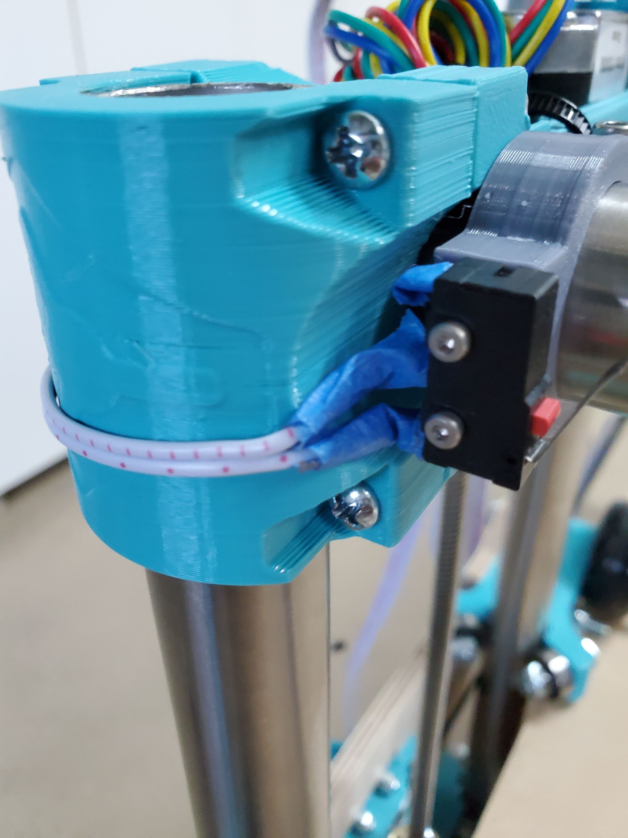
The Y limit switches were another beast all together. These limit switches were literally nestled underneath the entire carriage in a space that is literally 1 and a half inches wide and has the belt going through it. Putting the limit switches was a MASSIVE pain. Everytime I put the screw in, I wouldn’t have the dexterity— to be fair very few others would either— to get the allen key and hold. After that getting the screw to go through the limit switch into the hole in the plastic also took a lot of trial and error. And as a cherry on top, as soon as I thought I was done with 2 of the holes, the limit switch literally fell out, this was because the bolt that I was using didn’t go through the entirety of the plastic. I had to swap from M2 - 10mm to M2- 12mm, luckily I caught this with only one hole. After spending literally 75 min putting 4 screws in (that’s not an exaggeration), I was FINALLY done with all of the limit switches. The only thing I hope is that now I don’t fry them using the wrong plug (I have actually plugged it in without power into the wrong plug, but that is purely due to how closely the pins are.) Anyways, this is what the Y axis limit switches look like— hopefully you can appreciate my plight.
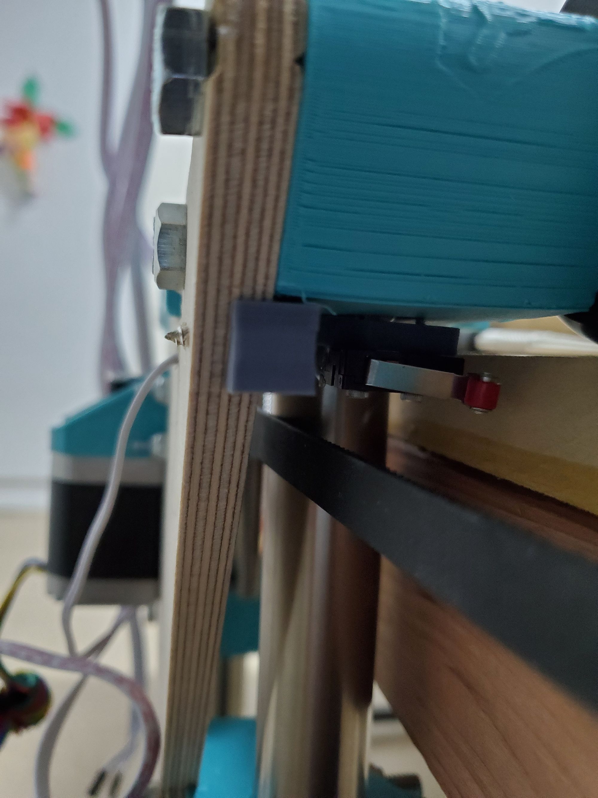
After pretty much burning through the day attaching 5 limit switches, I decided to try something different, I took a few “Glam Shots” of the CNC at this stage. Here are a few of the images I took.
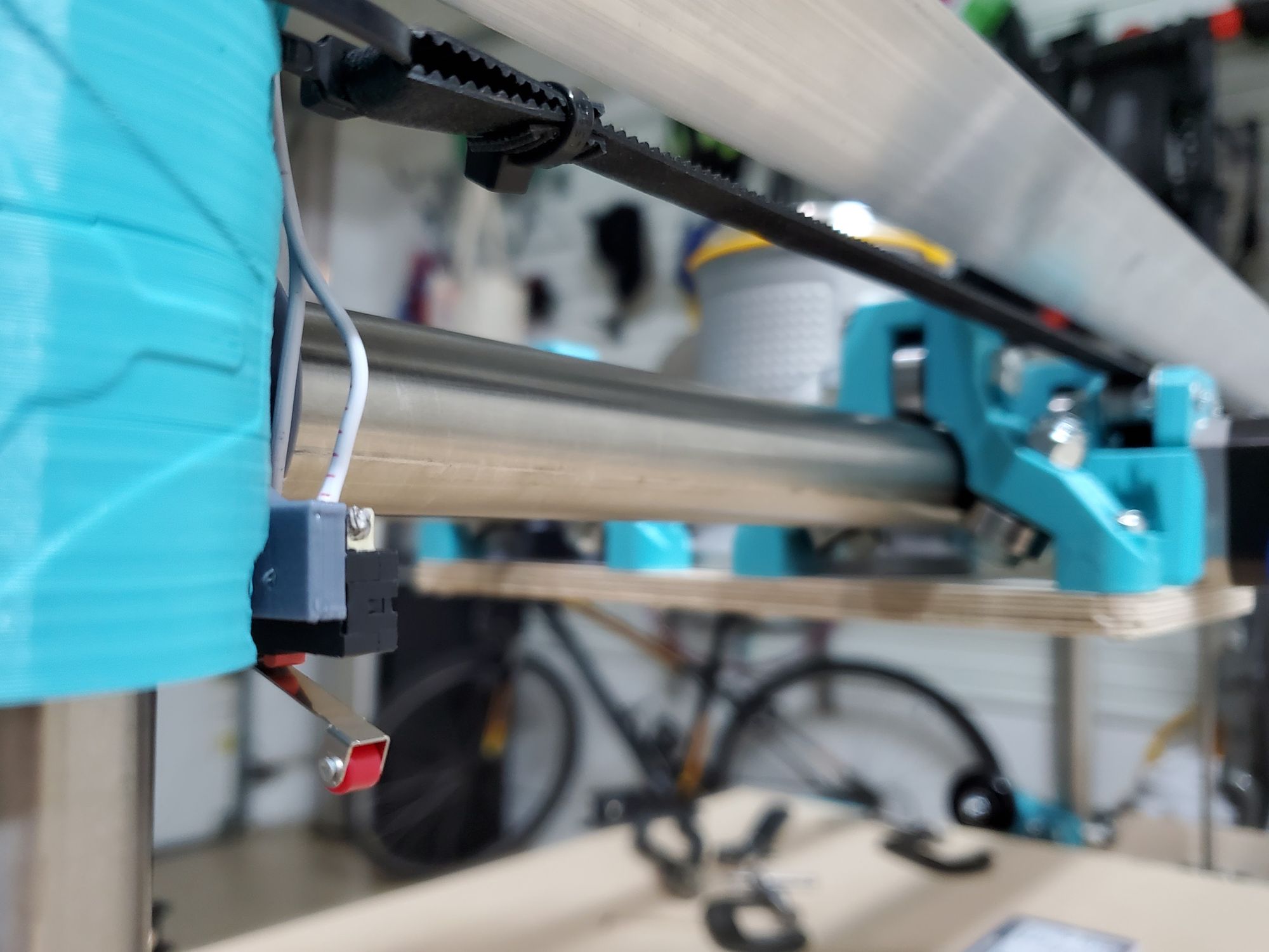
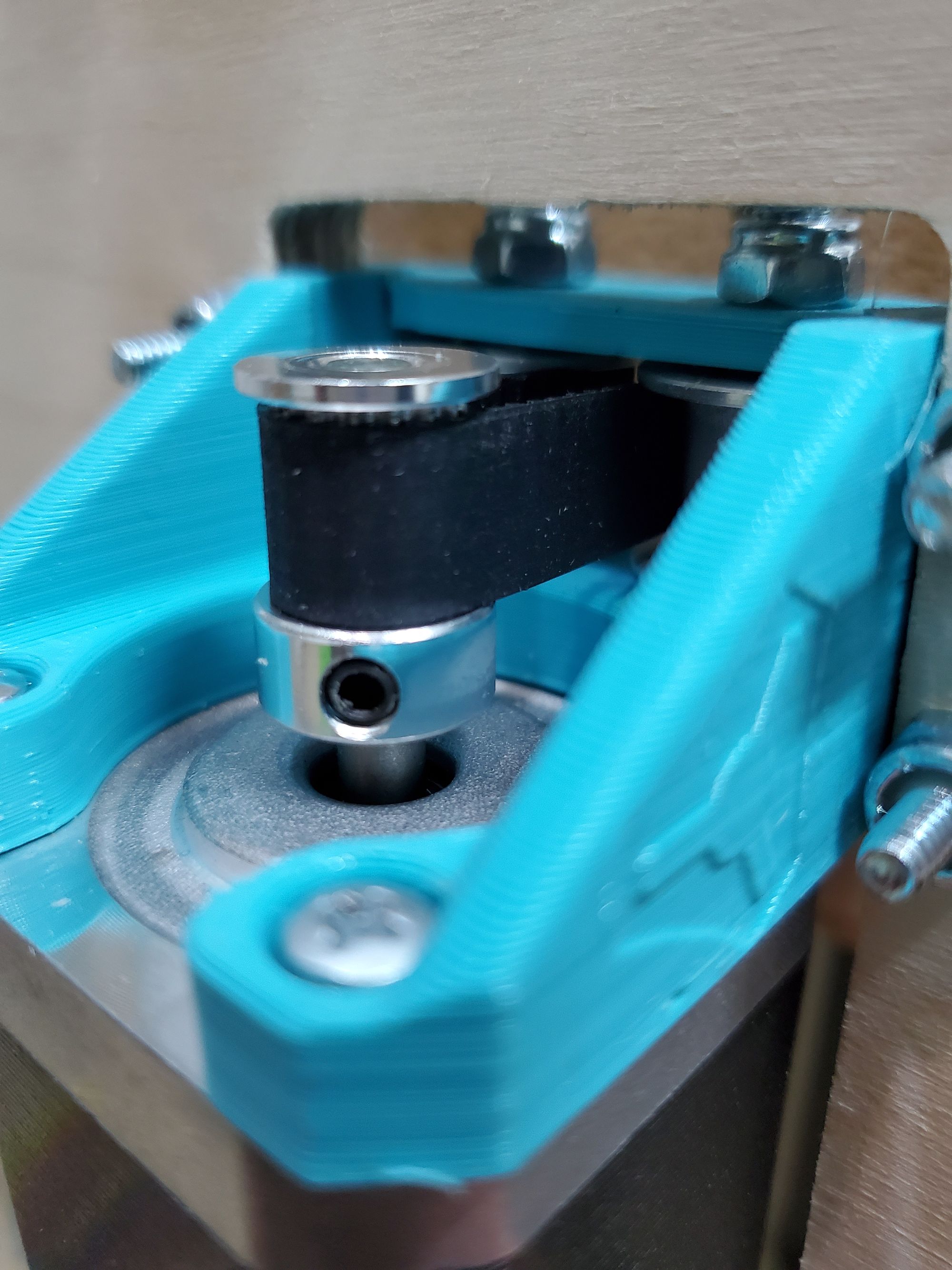
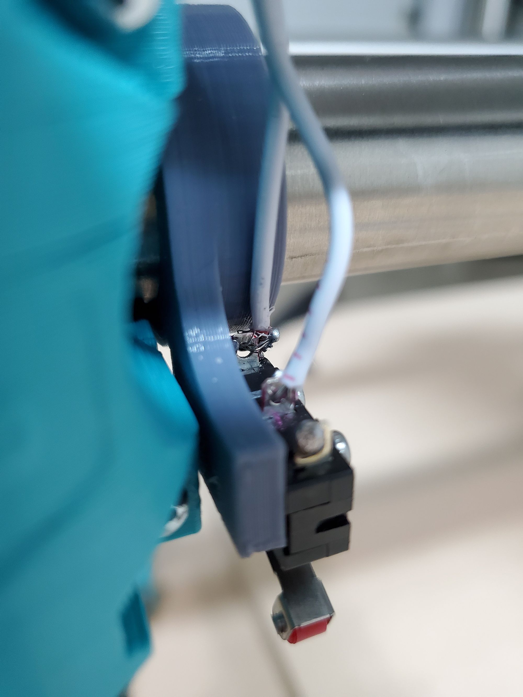
Time to work on testing and firmware!
Day 9: 1/22-23
The next order of business was to start actually wiring things up! I have spent so much time in the area that I was comfortable in, now wiring is an area outside of my comfort zone....
Call it laziness or whatever, I haven't gotten around to the rest...
]]>
Ah yes, Coronavirus, on a mission to restrict our summers... Here’s everything that I can remember happening: Bushfires, Kobe, Covid-19, Trump’s Impeachment, BLM, Stock Market... I probably forgot a bunch of stuff, but whatever; I sincerely hope the worst is behind
]]>Written between Jul 22-26, 2020
Ah yes, Coronavirus, on a mission to restrict our summers... Here’s everything that I can remember happening: Bushfires, Kobe, Covid-19, Trump’s Impeachment, BLM, Stock Market... I probably forgot a bunch of stuff, but whatever; I sincerely hope the worst is behind us.
Last year, I went up to Henry M. Coe State Park to capture the milky way, this time I want to up my game, raise the bar. This year, just around the same time as the Milky Way will be primed to be shot another phenomena will be visible, C/2020 F3 (colloquially known as NEOWISE, named after a mission by the Wide-field Infrared Survey Explorer (WISE) space telescope). Of the many comets that are projected to be visible, NEOWISE is one of the few that will actually reach Earth and be visible, at least until it sees the appalling state of humanity and decides to get as far away as possible. Until that day comes, which should be by the end of the month, I have the enticing opportunity to paint both the Milky Way and NEOWISE on my camera’s sensor.
My methodology for finding a place to take photos hasn’t really changed, but I have added a few things for particularly NEOWISE:
Location must not be crowded - Social Distancing y’all!_(Edit: Given the popularity, I guess this is an unavoidable reality, all we can hope to do is stay clear from others and arrive early. _- Location/Timing must have both NEOWISE and the Milky Way visible - 1 trip is better than 2, also traffic might be an issue.
- Distance from home - Due to COVID mandates, we shouldn’t be travelling too far.
- Skytracker w/ NEOWISE - Milky Way can easily be identified by the teapot (Sagittarius), NEOWISE?, not so much.
- MASKS & Food
I decided to go to the Silicon Valley Vista Point, which is near Russian ridge on Skyline Blvd. The amount of people here was crazy! I did not expect this many people to be here, given the state of the world. Luckily, we found a place near the entrance of a prominent hiking trail that had a pristine view of both NEOWISE and the Milky Way. You wanna take a photo of NEOWISE? Look up; You wanna take a photo of the Milky Way? Turn around.
I did not expect NEOWISE to be as small as it was, I could barely see it. With a decent camera, it was much easier to spot. This is a photo that shows NEOWISE, it is right below a star in the center, it almost looks like a star.

I realized that taking photos of NEOWISE would mean that I need much better equipment that I already have, this would also be quite expensive. Given the circumstances, I’m still happy with the photo that I got.
Here is just NEOWISE:

Now was my time to shine, time to take photos of the Milky Way. Rather than going for long exposures and multiple different shots, I decided to take as many photos in the same position as possible. I also reduced the exposure as I am going to try image stacking. The images that came out of the sensor were really dull, but I kept on going. Here is one of the unedited photos:

After taking the photos, we went back home and now it was my turn to edit the photos.
Last time I only used Lightroom for the image editing and then Photoshop for any other changes that I wanted to make (ie: stitching). This time I downloaded the free software, Sequator, and started playing around with the settings. I imported the images in Lightroom and started playing around with the settings, like I did last time; also like last time, the resulting image was quite similar.
After doing this, I took all the images that matched in composition. I made a “stack” of these images and imported them into Sequator. I realized that I needed a bunch of “noise images”, these are used (presumably) to teach the software how my camera creates noise and looks for patterns. From these images, it can then apply an “inverse-noise” filter. I think this works extremely well compared to other noise removal techniques, other filters do remove noise, but end up removing a lot of stellar data in the process; this method doesn’t do that. I then started going through the rest of the settings, here is what they do (to my knowledge):
- Base Image/Star Image - The images to be stacked
- I had 14 of these
- Noise Images - Used to intelligently remove noise w/out removing stellar data.
- I had 6 of these
- Vignetting Images - Like noise images, reduces vignetting
- I didn’t use this
- Output - File to output to, whenever I changed a setting, I would “render” a file w/ a different name
- I used .tif for lossless quality
- Composition - How to stack the images
- I used the freeze ground as I wanted the foreground to remain sharp, this meant I had to mask the foreground using a brush.
- Sky Region - How to process the sky
- I used irregular mask, this allowed me to specify the sky using a brush
- Auto Brightness - Do some editing for me, change the brightness
- I left this unchecked as I am going to post process
- High dynamic range (HDR) - This makes the image pitch black, but preserves a ton of info
- This is the secret sauce, it gives a ton of depth to Lightroom to work with
- Reduce dynamic noises - Hot Pixel reduction
- I did a few w/ this and a few without, a subtle change
- Reduce distortion effects - Reduce smearing
- I left this enabled with the complex setting, I wasn’t using a telescope lens.
- Reduce light pollution - Witchcraft; Amazing; What?!?! - This removes most of the light pollution, giving the image a ton of depth.
- This worked wonders as i assigned a sky region, it made the sky black rather than a washed out grey.
- I used the “I.A.A.” option, according to the website this, “analyzes the color tone of light pollution, and try to find polluted foreground regions, reserve more foreground details.”
- Enhance star light - Does what it says, does it well, what more could you ask for?
- Works well due to the mask for the sky, adds vivid depth to the stars
- Merge pixels & Time-lapse - I find these superfluous (Disabled)
- Color Space - sRGB
- My monitor isn’t accurate enough for Adobe RGB
Whew! That was a lot of settings! The output image weighed an impressive ~300 MB. I wasn’t expecting much from the image stacking. I expected something on the order of what a “water connoisseur” would say about different types of water; I expected something that’s basically imperceptible and for the 100 people who can appreciate it, good for you! Oh boy was I wrong!
Immediately when I moved the slider I noticed a HUGE amount of detail that I never thought possible! WHY hadn’t I thought of this before?! After doing my editing for the images (I covered my “methodology” last year, it remained pretty much the same), I showed the image to a few others, like myself, they were having a hard time believing that I took these pictures.
Without any further ado, here are the photos that I took!


On each of the images I focused on a different aspect: the foreground, the bright yellow cluster, and the nebulous purple area. Additionally, the 2 standout stars on the left are Jupiter and Saturn.
I also posted these photos on my Instagram:
I can’t wait to go again! This time with better circumstances, better equipment, and hopefully to a more exotic location— I’m looking at you Mount Diablo!
]]>


Written between Jun 8-11, 2020
Summer Break is like one long weekend, this is one of the projects that I observed and found really interesting was the installation of a fiber optic cable at home for the internet. We were using a comcast subscription and had maxed out the speed quota, 100/10 (this means 100 mbps down and 10 mbps up). AT&T fiber promises 1000/1000! That is 10x the download speed and 100x the upload speed of what I previously had!
There is a terminal right behind my mailbox, this terminal has all of the fiber for the 4 houses served by the mailbox. A technician came and ran 2 wires to an outlet in our house. One across the sidewalk and parallel to the control box, then one connecting the first wire to the outside control box. The problem that arose was that there was no power to the control box outside, this meant that we either had to bring power outside or we had to snake the cable upstairs to where there is power. The better option is to bring the fiber up, but the contractor was unwilling to do this. We ended up just closing shop and started pondering solutions.
We looked into POE and other crude methods to bring power down. In a vain attempt to check if there was a connection between the top area and the outside control box, I used some old 3d printing filament and ran it down, due to the flexible nature of the filament, it just coiled up and nothing was discovered. We hoped that the next person would either condone our macgyvered solution or be willing to try fishing the cable through the wall.
Luckily the next person that came was a kind filipino soul who was really willing to try anything and had an air of confidence around him. He seemed knowledgeable and was willing to try risks and unlike the other person who came, he trusted my dad and I and was willing to try to snake the cable through. This eventually worked and knowing that this was possible was both a relief and mildly infuriating as we could have had all of this figured out a few days ago.
After snaking the cable up, the fiber optic cable was terminated and turned into copper. The signal is then sent downstairs underneath the TV to where the modem and router are, the signal is then split into 4 networks, the best way to describe them are the following:
AT&T Router - Speeds of ~950/950 wired
- “Unsecure Devices and Entertainment” - This was both wired and wireless and is used by most devices at home (phones, laptops, etc)
- “Guest” - The guest network, wireless only
The Apple router - Speeds of ~300/300 wired (not gigabit capable, upgrade soon)
- “Secure user devices” - This is basically the entire house’s ethernet and is used by laptops that are docked (mine and my dad’s) and other devices such as the Raspberry Pi’s. Both wired and wireless.
- “Secure devices” - Wifi devices that need to be isolated.
The Apple router signal is sent back upstairs into a network switch which then supplies ethernet to the rest of the upstairs. This topology took a while to figure out, but it seems to work quite well.
The thing that baffles me the most is just how thin a fiber optic cable really is. The shielding makes it seem impossibly thick, but in reality it is so thin, you can barely see it. Here’s a photo of it unshielded:
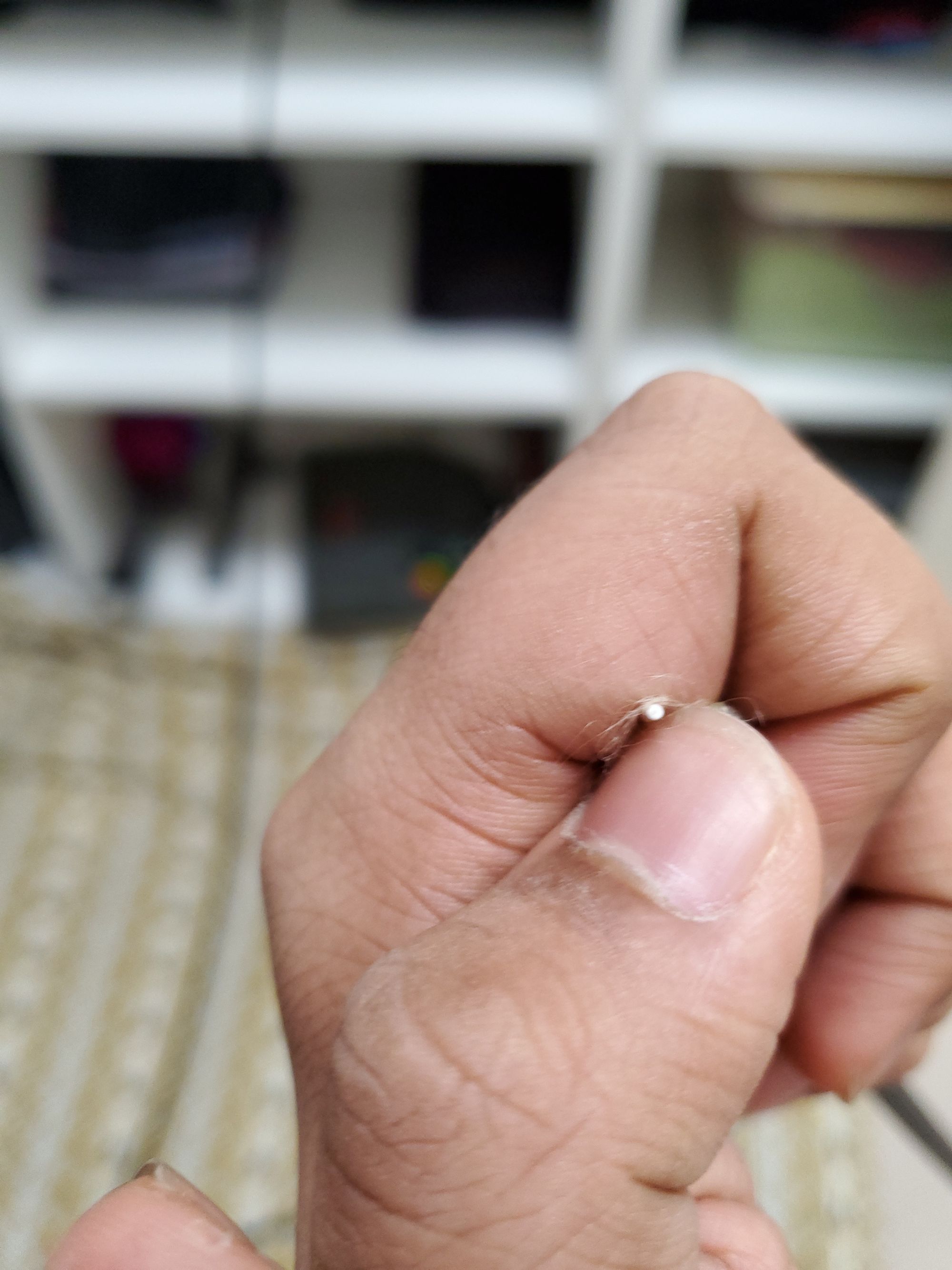
The fiber optic cable isn’t the white thing, it’s about ~9 pixels in size inside the white cable! My phone was barely able to capture it! *This photo is from an offcut piece.
I thoroughly enjoyed this project because I learned a lot about fiber optic cables and how they are routed. Here is a really cool video that I watched and learned a lot from.
]]>The Idea:
Written on May 1st 2020
When Covid-19 first struck it disrupted our entire way of life: no more in-person school, meeting with friends, politics, healthcare, etc. There was little that I could do to help, and this feeling of helplessness made me extremely uncomfortable. If the world is gonna stop, that doesn’t mean that I also need to stop, I need to pick up the pace and make the best of my quarantine. I looked back through everything that was happening to see if I could do anything: schools closed, can’t do anything about it; friends socially distanced, hang out using the internet; politics, advocacy won’t do much given the circumstances; healthcare, well maybe there is something that I can do here...
I started scouring the internet looking for ways to help front line workers...make masks, volunteer, print face shields, donate, advocate—wait go back, print face shields? I can do that! I had just gotten my 3D printer, and my lust for printing things was not even close to being satiated. I started my research by going to prusaprinters.org and seeing what the good folks at Prusa Research were doing. I was blown away by the impact they had, close to 100,000 face shields were going to be delivered in the next few weeks! I suddenly became extremely inspired, this was something I feel compelled to do, not for my sake, but for the sake of others! I immediately started sketching what I needed to do to organize something of the sort, during the course of my research, I stumbled upon the website of Makers Nexus, one of my friends who also had a 3D printer said that he used to go there and knew that they were doing something with Covid-19. After filling out all of the required forms I had my task, make as many face shields as possible.
The Execution:
Written on May 4th 2020 (May the Force be with You)
I just received the files to print and each of these parts for the face shields take ~20 hours! That means that I can only do ~40 or so a day, which is horrible efficiency. The slicer profile they provided brings this up to ~52 in 24 hours, let me see if I can make this better....
Well that was pretty fun, trying different settings to try to increase the printing speed of the mask. One of the 3D printing YouTubers that I watch, CNC kitchen, published an extremely helpful video with a lot of helpful tips and tricks. Using these and making a deep dive on the settings of the slicer I was able to boost the number of masks from the Maker Nexus profile of 37 parts every ~17 hours to an astonishing 37 parts every 7 hours and 28 min!
Here are the tweaks that I made to speed up the process:
- Remove all infill - the closely spaced line needs to be approached slowly, rather than using solid infill, use 0%.
- Max out the perimeters - By setting this to an obscene number (I set it to 8), the entire model will only be consisting of perimeters, these being long curves allowing the printer to accelerate to a much higher average velocity.
- Bottom Solid Layer = 3 ⇒ 2 - This is all that is needed, this is a necessary slowdown.
- Increase the Layer height (use variable) - Allows for 0.32 thick layers where there is low detail and this goes down to 0.2 mm layers when detail is needed. Manually controlling this gives unparalleled quality and plaid speeds.
- Disable Skirt - Manually watch the first layer, allows me to fit one more part.
- Add brim & turn up first layer speed - brim adds ~3 min, speed increase removes ~15+ min. Need to do both for reliability.
- Tune Speeds - Push machine to the limits (~80-120 mm/s)
- Increase Extrusion Width - The secret sauce allows you to have thicker layers (in the XY direction). It also allows you to:
- Remove gap fill - Takes too long, machine needs to go <30 mm/s. This reduced ~4 hours with Extrusion Width!
- Increase Temperatures - Stronger layer adhesion, reduces surface quality but this doesn’t matter
- Level Bed - Ensures perfect adhesion.
- Set up a schedule for printing, and count filament usage - This allows the machine to pump out as many parts without having filament runouts. My schedule was 7:30AM —> 3:00PM —> 10:30 PM—> Repeat. I can do 8 prints on a spool.
With all of these tweaks I am able to do 3 sets of 37 each day, even accounting for the occasional failure this means that I can do ~110 a day—a HUGE step up from the ~52 that Makers Nexus’s profile allowed me to do. After sharing this profile with others, people were also able to drastically increase the number of face shields that they can produce each day. After printing my trial batch, I dropped this off today and got some blue filament to print more from. Here is a short video of my printer printing the initial black batch.
My second batch was a batch of ~300. This is one of the last batches that I took a photo of.
Written May 12th 2020
The friend that initially informed me about Makers Nexus just let me know that he has also been printing components! Together, we recruited another one of our mutual friends and we all have been trading tips, discussing techniques, and just talking about things every so often. Our goal as a collective is to print ~3k components. I also set up a camera for monitoring, this camera can also do timelapses, though it isn’t meant to do this. I have attached all current (and will attach all future face shield timelapses) at the end of this post.
Written on May 20th 2020
Since the last entry I have delivered 2 batches as I got 2 boxes of filament (you can see them in the previous picture). This brings the total that I have delivered to 150 (initial black) + 297 (blue) + 278 (pink) + 296 (pink). This means that I have delivered enough parts for ~1021 face shields! Barring the ~5% failure rate of these, that means that I have delivered ~969 components! I picked up 1 more box of pink and a box of white and will start printing once I get home! (This was written on my phone on the car ride back from Maker’s Nexus).
Written on May 26th 2020
I just received an email from Makers Nexus stating that they have fulfilled ALL of their orders! My final tally (with the batch that I just dropped off) is 1207 components! While I didn’t contribute as much as some others did, people who had larger printers and multiple printers, I feel very proud knowing that I contributed ~1.2k components of the ~160k 3D printed components needed (each shield is 2 printed components and one visor, one of the printed components was replaced with an injection molded component around May 16th). Of the components that I contributed, I contributed ~1k of the ~80k components that they received!
Written on May 27th 2020
After speaking with my friends, we ended up producing a bit more than our goal of 3k! This is really exciting for me and I feel much more confident going into the summer Covid-19! We have all played a part in helping healthcare workers stay safer in the front lines. I am more motivated than ever to continue using my 3D printer to create new and exciting things, things that benefit not only myself, but thousands of others. This experience is one that I will never forget and has cemented to me the power of a 3D printer.
Final Batch Photo:
Timelapses (I turned these off for night shifts and often forgot to turn them back on, these are mostly the first 300 or so face shields):
covid19-shield-37pc_0.3mm_PLA_ENDER3_14h38m_20200503003725.mp4
covid19-shield-37pcV2_0.32mm_PLA_ENDER3_9h21m_20200503193225.mp4
covid19-shield-37pcV2_0.32mm_PLA_ENDER3_9h21m_20200507224756.mp4
covid19-shield-37pcV2_0.32mm_PLA_ENDER3_9h21m_20200508220501.mp4
covid19-shield-37pcV2_0.32mm_PLA_ENDER3_9h21m_20200509184711.mp4
covid19-shield-37pcV2_0.32mm_PLA_ENDER3_9h21m_20200511164249.mp4
covid19-shield-37pcV2_0.32mm_PLA_ENDER3_9h21m_20200512204619.mp4
covid19-shield-37pcV3_0.32mm_PLA_ENDER3_7h22m_20200520150249.mp4
The occasional fail:
FAILED_covid19-shield-37pcNEW_0.32mm_PLA_ENDER3_9h20m_20200513170214.mp4
]]>Written Jan 1 2020
Happy New Years! Can’t wait for 2020! 2020 is a year that I think everyone has been looking forward to.
I spent my winter break primarily working on my torrent/media server and enjoying my vacation. I think I’ve gotten my server to a place where it can fetch and dispense media to my liking— more importantly, my parent’s liking.
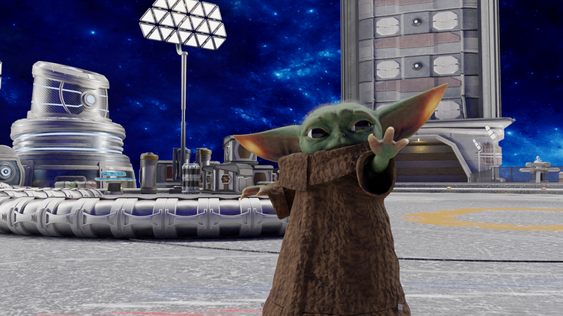
Baby Yoda is SOOOO cute. I literally cannot. I was browsing through instagram and saw that @beeple_crap had posted a model of baby yoda that was fully textured and rigged.
I have used blender in the past, but I am by no means an expert at the software. I decided as a good way to produce a result and learn was to use the Baby Yoda model and make it look cool.
I spent a few hours playing around with the model, seeing the limitations and trying to get Baby Yoda into a position that I found interesting. After that, I found a generic scene. This was a scene of an abandoned house. I created a render of this, but found the results underwhelming. With my new(ish) computer already coughing and puffing, I decided to crank the background to 11.
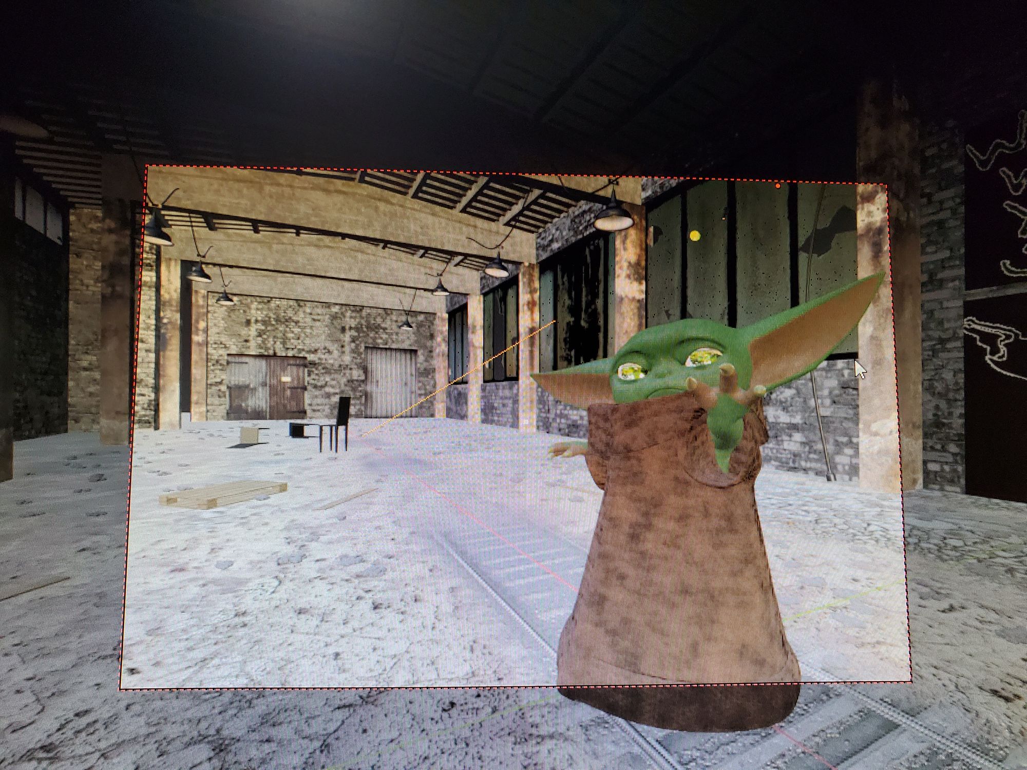
I didn’t end up liking this background. It made it seem as if Baby Yoda just murdered someone or something, idk.
I found this really cool space themed background. It has a cool vibe to it. It also goes with the Star Wars theme. I spent a while adding and removing assets from the template. After I played around with moving Baby Yoda and trying a hundred different things, I finally got the result that I wanted.
Here is it rendering!
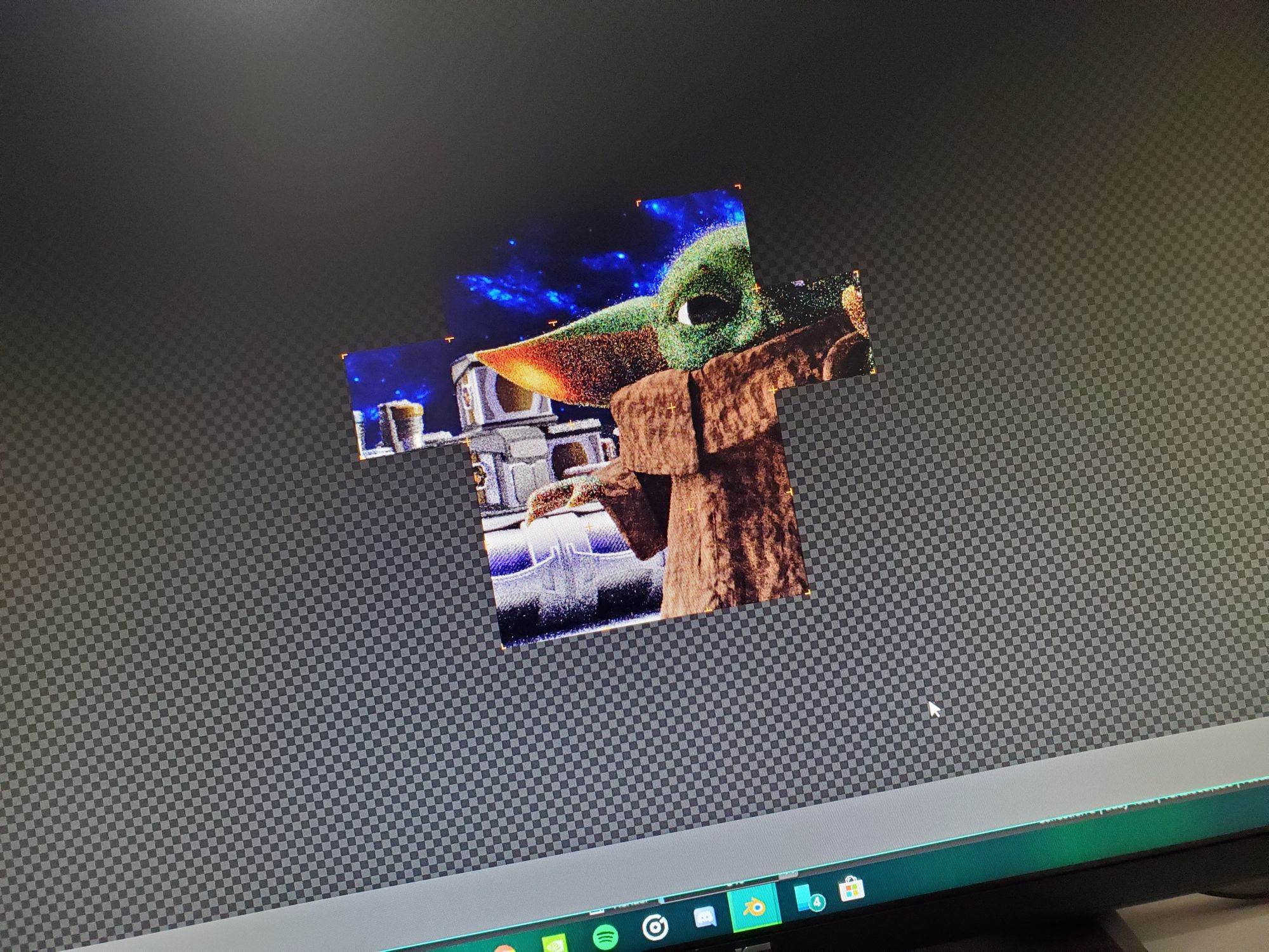
After I got the final render, I cleaned it up in Photoshop and really got Baby Yoda to shine.
Here is ~30 hours of efforts and a render with 1000 passes:
